
Auto to 6spd transmission conversion
Auto to 6spd
Transmission Conversion
By
Mohd A.
Last updated
2/7/2003
Auto

–>

6-spd
This is a guide for
Automatic to 6-speed transmission conversion for the 93-98 Supra Twin Turbo,
with many installation photos. I’m assuming you already have the basic skills to
remove and install transmissions, if not then get someone to help you. Most of
the tools you will need are the basic transmission tools commonly used. Also
each section will list all the parts needed to finish job. You may or may not
have all the parts needed, check your parts before starting. I highly recommend
the Toyota repair manuals for this job, Here are the steps according to the
order I used,
-
In Cabin Modification,
Click Here. -
Raise & Secure the Supra car,
Click Here. -
Removal of the Auto Transmission,
Click Here. -
Modifying the Sub-Tunnel,
Click Here. -
Installing the 6spd Transmission,
Click Here. -
Removing & Installing Differential &
its related parts, Click Here. -
Engine Optional Part, Drive Belt Tension
Damper, Click Here.
FAQ:
1) How much will
this swap cost me?
it can cost you from few hundred to few
thousands dollars, it all depend if you get your parts new or used,
The major cost is in the 6spd transmission, clutch system components &
differential parts. Also depends if you hire someone to do the work or save the
money and do it yourself, that’s if you are up to the task.2) How long will it take?
it can be done in
two days, a week or a month, all depend on your skills, tools, availability of all needed parts,
and how much help you get to move on faster, I recommend to think it through and
give yourself lots of time to get the project right, the extra time you give
yourself will let you reflect on your work.3) Can I use the auto
differential?
Yes, but :-), the Auto differential ratio is 3.769, the
6spd differential ratio is 3.133, you will also need to use the auto drive shaft,
and need to extend it, gets
extended almost to the edge which gives it about an inch to hold on to the
shaft, this is how it
would look if its in a normal setup
(not extended), as you can see, its up to you to decide if its safe or not.if your planning on
permanently using the
Auto differential then find a used 6spd front dive shaft.
it will be safer in the long run and will fit like stock.
I did drive my 6spd supra for few weeks on the auto
differential, the gears felt very short, the Speedo was about 15-10 miles off,
the Engine temperature was a littlie above normal, 1st gear was useless, 6spd
gear on the highway could not give me a good speed without pushing the rpm
higher, in return poor gas mileage, in general I hated how it felt, I
recommend strongly the 6spd differential, Also if you do get a Japanese spec
6spd differential it will be about 3.26.
![]()
![]()
racelogic traction control installation
Racelogic Traction
Control Installation
By
Derek Wang

This article explains in detail the installation
of the Racelogic Traction Control System on the US Spec MKIV Supra. This
installation article was based on a US Spec ’94 Turbo Supra with TRAC. Other
years, models, and country models may differ. Please consult your factory
service manual whenever possible
To get your own Racelogic Traction
Control in the US, contact Matrix Engineering as they’re the exclusive distributor for the
RLTCS in the US.

Tools Needed:
10mm socket wrench
Wire
cutters
Razor blade
Phillips screwdriver – Various sizes
Flathead
screwdriver
Soldering iron
Overview:
The Racelogic System monitors wheel
speed independently and looks for a difference in wheel speeds larger than a
predetermined (but tunable) threshold. Once the threshold is met, engine power
is reduced by cutting each of the six injectors independently in a rapid cycle.
They system can be adjusted to give a desired level of slip (5%, 10%, 15%, 20%,
etc). Optional features include launch control, full throttle shift, and
adjustable rev limiter.
The wires we will need to tap into are the six
injector wires, the four wheel speed sensor wires, RPM wire, ignition power, and
ground. The adjuster controller will also need to be connected via three wires,
and a serial cable can also be used to interface with a laptop computer for
data logging and additional tuning.
Installation:
Disconnect the negative battery
terminal before working on any electronics on the car
Expose the ECU in
the passenger footwall by removing the plastic carpet trim which runs along the
rocker panel under the door. This will allow for the carpet to be pulled back
after the removal of a few plastic buttons, exposing the ECU cover. Remove the 2
10mm nuts securing the cover then remove the cover. You should now be able to
see the ECU and the factory TRAC computer.
Unplug and remove the TRAC
computer. You will no longer need this with the Racelogic Traction
Control
Loosen the 10mm bolt holding the twin harness plugs onto the ECU
and remove the plugs for easier access to the six injector wires. Find the
injector trigger wires E9-15 to E9-20:

These wires will
need to be cut, one side going into the Racelogic, the other side connected to
the output of the Racelogic:
From ECU side, connect to: Red, Orange,
Grey, Green, Yellow, and Pink wires of the RL.
From firewall side, connect
to: Red/Black, Orange/Black, Grey/Black, Yellow/Black, Pink/Black.
Make
sure each injector wire has the same solid color on the ECU side as the color
striped wire to the firewall side. It is not important which color RL wire
connects to which injector
Shown below is the wiring via a Fields ECU
harness. I recommend soldering these wires and using shrink tube to protect them
from exposure:

Find the RPM
signal wire, E9-58 (Igniter), and tap the Racelogic’s black/white wire into this
signal. You do not need to cut this wire. You can use a razor blade to strip the
sleeve off a small section of the wire, then solder the RL wire and carefully
tape this up with electrician tape.
*Alternate RPM wiring –
If your car has additional
devices like the HKS VPC, Apex’I S-AFC, or any other piece that is already
attached to the E9-58 igniter RPM wire, you may experience an RPM signal drop
which will cause the Racelogic to malfunction. A good alternative is to use the
E10-16 (TACHO) wire on the ECU harness for the RLTC RPM wire:

Connect the RL’s
power wire to an ignition switched power supply. This can be found on terminal
E10-1.
Ground the RL to a good chassis ground. I used one of the ECU
mounting posts by sandwiching the RL’s ring connector on the ground wires
between the chassis, and the 10mm ECU mounting nut. Make sure you get a good
ground connection here by removing any paint that may interfere with the ground
point.
Now we’re ready to wire up the remaining four wheel speed sensor
wires. Expose the ABS/TRAC computer by removing the center dash trim pieces.
First, remove the trim piece around the shift lever by firmly pulling up on the
panel:

Next, remove the
odometer cluster by removing the small screws holding the cluster onto the top
of the dash:

Remove the main
trim piece which holds the clock, and the HVAC controls. Remember to unplug the
clock, the HVAC plugs, the cigarette lighter, and the traction control
button:

With the trim
panel removed, remove the radio and the ABS circuit box and antenna relay:

This exposes the
ABS/TRAC computer which looks like this:

Unplug the left
and the center connectors, then route them out of the dash on the driver’s side.
This will allow for more room to do the wire taps. Also, route the RL’s wheel
speed sensor loom from the ECU area to the driver side footwall by going through
the center dash:

Find the wheel
speed sensor wires on the plugs which are now in the driver side footwall. We’re
looking for the (+) wheel speed sensor wires (A20-5, A20-17, A21-2, and
A21-9):

Click here for diagram of cars without TRAC
Splice
into these wires with the four RL wheel speed sensor wires similar to how you
spliced in the RPM signal wire. The order is not important:

Reconnect the
plugs back into the ABS/TRAC computer:

Find an
appropriate place to install the selector knob/launch control button. Reinstall
all panels, covers, carpet, and trim in reverse order of removal. Then you’re
done!
Testing/Troubleshoot:
Ensure
all wheel speed sensor and RPM wires are connected correctly by monitoring the
green LED on different slip positions on the selector knob. Starting from “WET”,
the first 4 settings on the knob indicate wheel speed sensor input. When each
wheel is spinning, the LED will flash according to wheel speed. The faster the
wheel spins, the faster the LED blinks. Select between all four of the settings
to monitor each wheel individually. If one setting does not show a flashing LED
while the car is moving. Check your wheel speed sensor wiring.
Test the
RPM signal in a similar fashion by turning the selector to “OFF” or 20% slip.
The higher the RPM, the more rapidly the LED will flash.
Once the wiring
is confirmed, follow RL’s instructions for
calibration.
![]()
Other mods
| new readers rides system!! click here to put in your entry. |
 home
homeFuel system upgrade with 720 injectors
Fuel System Upgrade
Instructions
Big Thanks to Bryce Danna & Bruce St.
John
Ok, so I decided to go with a single turbo setup….now my
worry at the time was fuel…..I dont want to ever worry about running out, so I’ve
decided to upgrade the whole fuel system in my Supra.
Disclaimer: This page is for information purposes only, by viewing this web page you
agree that I am no way responsible for you screwing up your car!
Note:
This tech tip focuses on the basic install fuel system upgrade instructions.
Tools required
: You will need a good set of tools, mostly you
will be using 10, 12, & 14mm sockets & flat wrenches, screw drivers (phillips
& flat), hammer, etc, etc
Steps
:
![]()
Here is everything you need for this bad ass
fuel system
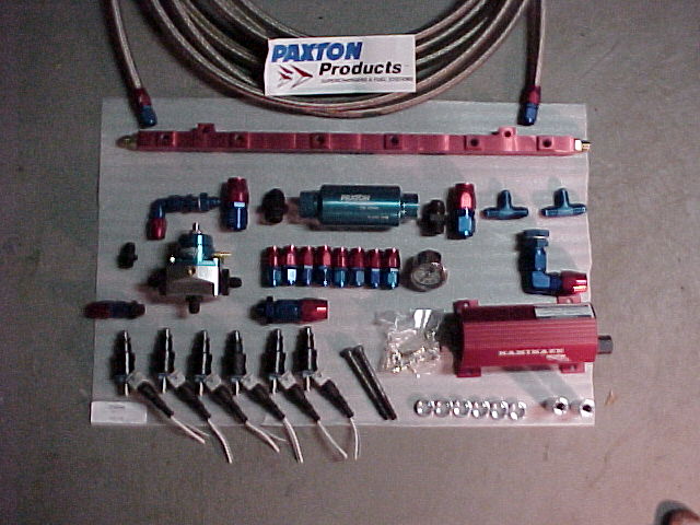
- (6) 720 cc injectors
- HKS Fuel Rail
- Paxton Inline fuel filter for turbo cars
- Paxton Kamakaze 750 Fuel pump
- 4ft of -10 AN highpressure hose
- 15ft of -6 AN highpressure hose
- (2) -6 X -6 X -6 AN T’s
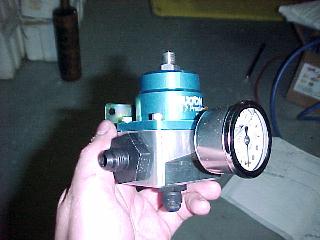
- Paxton Fuel Pressure Regulator w/ gauge
- HKS VPC (prom for 720cc injectors) – look at my page for
instructions on this - Lots of patience if your going to do this yourself!!
-
If you have the Toyota Supra repair manual,
that will help alot too!
For any bolts you cant break loose, definetly
get a can of this stuff….
Your also going to have to jack the car up on
all 4’s….or get it on a lift….
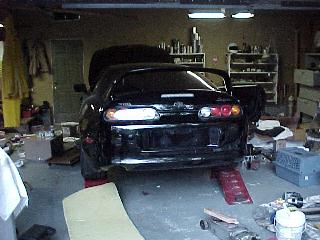
Here is an over view of the installation….

![]()
Here is how this is going to work,
We are going to drill a hole in the bottom of
the tank & run a -10 to the fuel filter….
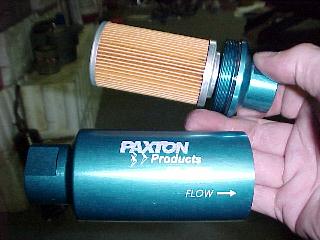
![]()
From the filter we run a -10 to the fuel
pump….
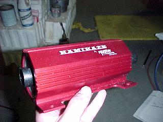
![]()
Now picture the rail with 1 1/2ft of -6 from
one end of the rail to the other….
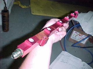
![]()
On this loop we are going to have TWO T’s (-6
X -6 X -6)
On one T is going to be the -6 feed from the
pump,
on the other T is going to be the FPR (fuel
pressure regulator),
From the bottom of the FPR we run a -6 to the
tank for our fuel return….
![]()
![]()
![]()
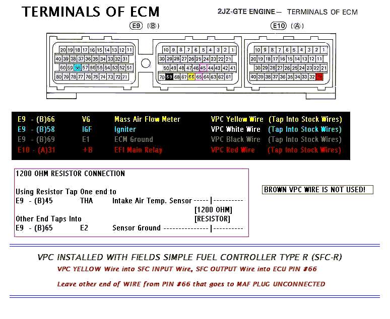
Vpc install instructions
HKS VPC Install Instructions
How
to Hard Wire the HKS VPC?
Note:
This tech tip focuses on the basic install of the vpc & not tuning.
Tools/Parts
Required:
Phillips screwdriver, sildenafil 12mm socket wrench, Needle nose
pliers, 10mm & 12mm flat wrench, Some zip ties, a small T, & a razor.
Steps
:
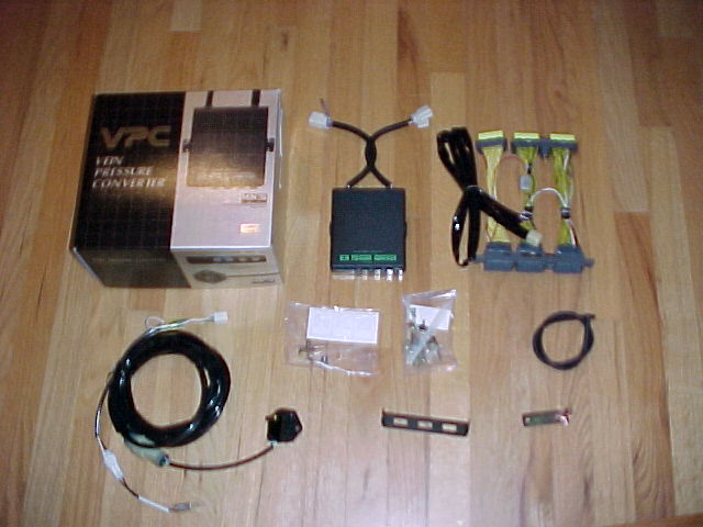
Here is everything that comes w/ the VPC – spent $950 w/
single turbo prom.
The stock MAF (Mass Air Flow) Sensor will be removed. Put
electrical
tape on the connector for the MAF & secure it
somewhere. It will no longer
be used. If you dont know where the MAF is, then you shouldnt be doing this mod!
You need to remove the scuff plate on the passengers side,
one black
snap (on the scuff plate), two phillips head snaps holding
the carpet down
on the kickboard. Remove the kickboard using a 12 socket
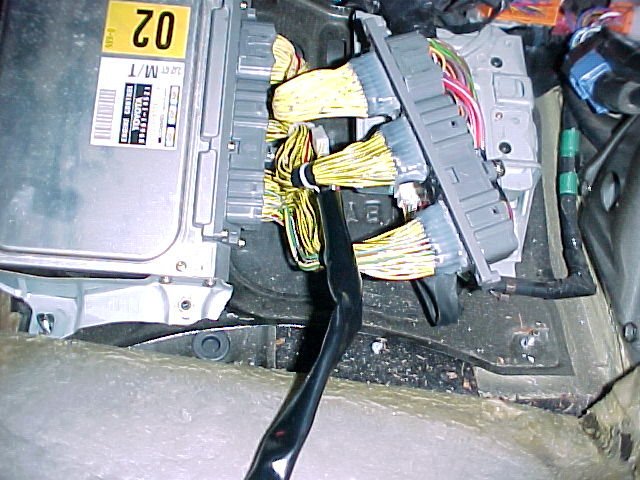
(2) 12mm nuts.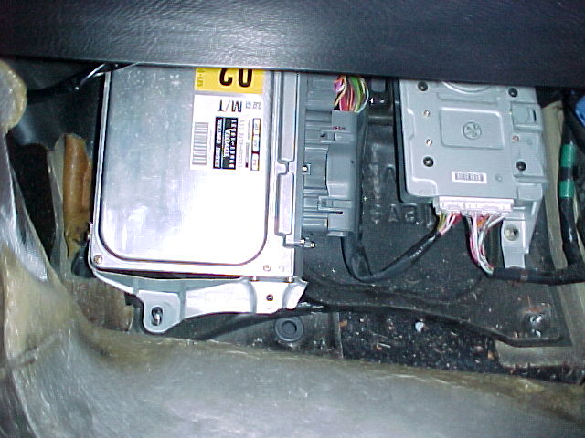
Disconnect the wiring
from the ecu, plug the vpc harness in…cake
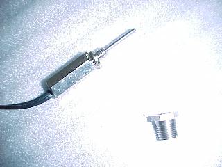
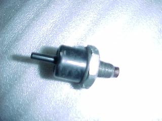
This is the vpc temperature probe
This is the stock gas filter, we need to remove it &
place the
temp probe here – its right next/below to the turbo
pressure sensor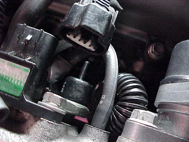
Here is the stock gas filter removed from the intake
manifold
This fitting replaces the gas filter. Screws right in w/ no
problems.
See the vaccum hose next to the fitting – this vaccum hose
will be
disconnected, pull the hose from under the intake manifold,
it will
later be used in a T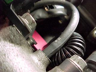
Now screw in the temp probe
The vaccum hose that used to be on the temp probe is out of
the picture, the nipple next to the temp probe will go to a
T
explained in the pic below. The other end is explained in
the
pic after the next.
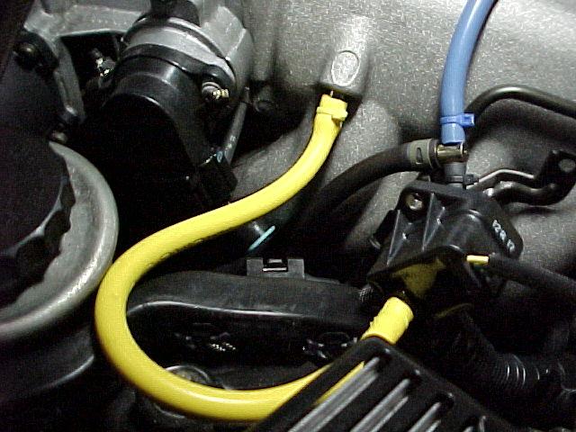
The vaccum hose from the power steering is disconnected,
this is
where our pressure sensor will be plumbed to. The power
steering
vaccum hose (just disconnected from the nipple on the
intake manifold)
will go to a T. The other end of the T will be run up the
intake manifold
to the white T pictured earlier. Remember the hose we
disconnected next
to the temperature sensor? This hose is connected to the
3rd part of the T
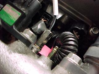
Here is a closeup of the vaccum hoses by the temp sensor.
Your vaccum hoses to the left of the T may have a different
arrangement because my EVC pressure sensor & HKS BOV
are plumbed to the stock T (far left) – so if your setup
looks
different left of the white T – dont worry about it.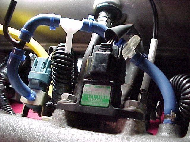
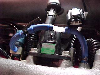
Here is the turbo pressure sensor connected to where the
power steering
vaccum previously resided (yellow hose). See the T? The
hose pointing
left is the power steering vaccum hose, the blue hose
pointing up is going
to the white T pictured earlier. The black vaccum
hose pointing down
is the hose off the nipple next to the temp probe. Did that
make sense?
Read it a couple times slowly 🙂
*The
1200 ohm resistor can be also connected from the MAF harness, much easier to
install that way.
VPC unit
Inside look
Dip Switches for the MKIV
VPC Prom for auto (AT), Stock
injectors


![twinturbokit[1].jpg (71394 bytes)](twinturbokit%5B1%5D.jpg)


![image058[1].jpg (96493 bytes)](image058%5B1%5D.jpg)
![imageNGL[1].jpg (97409 bytes)](imageNGL%5B1%5D.jpg)
![imageLFK[1].jpg (98199 bytes)](imageLFK%5B1%5D.jpg)
![imageR3C[1].jpg (58640 bytes)](imageR3C%5B1%5D.jpg)
![imageKRN[1].jpg (93733 bytes)](imageKRN%5B1%5D.jpg)
![imageNPU[1].jpg (63703 bytes)](imageNPU%5B1%5D.jpg)


Hks gt intercooler install photos
HKS GT
INTERCOOLER(IC) INSTALL PHOTOS
HKS GT IC(BACK) vs. APEXI
IC(FRONT)


APEXI IC ready to come off


HKS GT IC


HKS new power steering cooler


Coolant reservoir tank
relocation kit


IC mounting brackets


![]()


Hks gt intercooler install photos
HKS GT
INTERCOOLER(IC) INSTALL PHOTOS
HKS GT IC(BACK) vs. APEXI
IC(FRONT)
APEXI IC ready to come off
HKS GT IC
HKS new power steering cooler
Coolant reservoir tank
relocation kit
IC mounting brackets
![]()