
Rps turbo kit photos & install
RPS Turbo Kit install on 94 MKIV
By Kevin Goroway
[ SP-60 Kit ]
RPS Kit as supplied by Sound Performance
Note: The
dollar bill didn’t come with the kit… it’s there for size reference. 🙂


Here’s a shot of the HKS manifold just
for comparison.


Plug the water
line seen in the next picture. You may want to tie this whole assembly back as
close to the firewall as possible. Otherwise, the lower hose is dangerously
close to the downpipe when its all finished.
This next shot
shows the upper radiator pipe which I took off and had modified. There are
normally two nipples for water hoses here. They are right smack in the way of
the intake to the turbo. This is a very common problem with the RPS header. It
cost me a whole $40 at a local place. Finding someone who would weld aluminum
wasn’t easy, though.
Connect the oil
return line here:


Connect the oil
feed line here:

Plug the rear oil feed line
here:

Now came the hard part. I tried the
header, and it didn’t fit. It became clear that at least one of the bolt holes
didn’t line up. I’ve since found out that this is common with the RPS header.
You can see Mark, and Roberto trying to solve the problem with my dremel. We
quickly determined that gasoline powered cars would no longer be legal by the
time we would finish it this way… A Home Depot run later, I was the proud
owner of a 1/2 inch drill, and a bit one size bigger than the hole that RPS gave
me. Roberto muscled his way through the one hole that seemed to be the problem.
And, luckily, we were able to get it to clear all of the bolts. Caution: If you
need to do this, be very very careful. It takes quite a bit of force, and the
collectors are very close to the other side of the hole you are
drilling…


Here’s Roberto fiddling with the lower
back bolt. Because of the turn in that rear collector, the bolt basically has to
be threaded on as the header is pushed on…What a PITA.
It’s on! And the EGT probe is
mounted.

It was about now that we realized
that the kit was missing the bolts to connect the oil return line to the turbo.
It was also missing the long bolt for the sorta built-in clamp that is part of
the wastegate/downpipe. A quick run to the hardware store, and you can see it in
the second pic here. Downpipe, and Turbo installed.

Connect the oil feed line, and the oil
return line. Bolt in the primary O2 sensor. And the turbo is done. There is one
more radiator hose to plug. You can see it in the second picture above. It’s the
one right behind the water pump. You may also notice in the first of the two
pics above that my (black) upper intercooler pipe (part of the XS intercooler)
will certainly need to be cut. So, I went and bought one of these. 🙂 I didn’t
want to worry about shavings that would be caused by using a hacksaw, or
anything similar. This pipe cutter was perfect.


It was after this upper intercooler
pipe/blow-off valve combination was installed that I realized I was going to
have to tap into the pipe and install a fitting for a pressure source… I
needed this pressure source for my boost-controller/waste-gate. I wanted the tap
to look neat, so it’s under the pipe, where the blow-off valve is welded
on.
Next was the intake. Notice that I have capped the port in the intake.
This is supposed to take a hose from the port on top of the valve cover, as seen
here . But that will lead to oil in the intake track. Better
to just put a small breather up there.


Here’s a few shots of the inside of
the car. Next to the TRAC button you can see a switch I made for my
two-step.


This is where
the Apexi boost meter is tied up.

Here’s Henri
under the car tieing up my mid-pipe so I can drive the car to an exhaust shop
(loudly) to get a downpipe made for the new turbo.
![]()
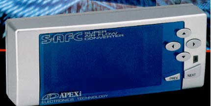
Apexi afc install instructions
A’PEXi
S-AFC Installation


Concept:
Entry-level fuel computer designed to modify the air flow meter signal.
Also
can be used instead of the GCC for finer control of your VPC.Characteristics:
Easy to read VFD display, unparalleled list of functions
Comments:
The second generation SUPER AFC follows the highly successful SUPER AFC in an
upgraded package. The SUPER AFC is a vehicle specific fuel computer that
modifies the air flow meter signal/ pressure sensor signal and allows the user
to either richen or lean the fuel mixture. Adjustment ranges from +/- 50%. The
Super AFC boasts an 8-point adjustable fuel curve with 500 RPM increment
setting points. The Super AFC also allows the user to adjust fuel enrichment
according to either LO/HI throttle positions. The AFC also cures the erratic
idle problems associated with open atmosphere blow off valves on hot-wire air
flow meter equipped vehicles. MONITOR MODE shows analog meter faces, Y graph
display, Numerical display, Peak Hold, Replay Mode, 1 point/10 point and ghost
map tracing. All correction factors are also displayed in percentages.
Here is
what you will need:–
S-AFC wiring harness and head
unit–
10mm socket–
Wire crimpers–
Butt connectors
and the supplied connectors
Lets
get started!1.Remove the negative
battery cable.
2.Remove the wiring harness
from the ECU.
3.Refer to the ECU diagram.

- Splice
the Green
Wire (RPM) into 58.- Splice
the Gray
Wire (Throttle) into 43.- Cut
wire 66 in half, leave yourself enough room to connect a wire to ECU harness.- Connect
the Yellow
wire to the 66 wire connected TO the ECU harness.- Connect
the White
wire to the 66 wire heading AWAY from the ECU harness.- Splice
the Brown wire (ground 1) into 69,
close to the ecu.- Splice
the Black wire (ground 2) into 69 at least 1cm away from the Brown
wire.- Splice
the Red wire (12V+) in to ECU wire 31.- Pink
and Orange
wires are not used.OK,
Now you have all of the wiring done, double check all of your
connections, reconnect the wiring harness
to your ECU. Make sure all of
those wires are still tight. Plug the harness into the S-AFC.
Reconnect your battery cable. Turn the ignition to the ON position.
The AFC should boot up and display A’PEXi, if screen did not light
up, stop disconnect the battery and find out what went wrong.
Most likely it is power or ground problem (or a loose ecu harness.)
If the
unit Powers On, follow these steps:First
start off by Resetting the AFC.
Many have often complained that their AFC does not show full
throttle(%100), regardless if
it is brand new. Go under [etc.] and
press NEXT~>. Confirm “YES” when prompted “Init.
All?” and
press NEXT again, Now turn the ignition OFF and then back ON, and the unit
should now be reset and ready.Next
enter the following basic settings:-Go to [main]
~>[setting] ~> [3. TH-Point] ~>
[Lo-94, Hi-95]-Go to [main] ~>[etc.]
~> [1. Sensor Type] ~> [1.
Hot-Wire] ~> [in-12, Out-12] ~> [in-1, Out-1]-Go to [main] ~>[etc.]
~> [2. Car Select] ~> [Cyl:6, Thr: UP]-Go to [main] ~>[etc.]
~> [3. Graph scale] ~> [Ne = 7000rpm][Ne-POINT = 3500, 4000,
4500, 5000, 5500, 6000, 6500, 7000][Dec. -Air = NOT USED, unless you
want to use it to compensate for venting your BOV to atmosphere]Do not modify the low
throttle settings. While at low throttle (in closed loop mode) the ecu
will counteract any changes made and over time your long term fuel map will be
modified. I recommend modifying your high
throttle fuel curve on the dyno with an air/fuel ratio meter & egt gauge
installed. For maximum power, one
probably wants to run an air to fuel ratio of between 11:1 (rich) and 12.5:1
(lean) Do
yourself a favor and pay a professional to tune it. If you lean your
engine out, things can melt.
Blue wire
mod info:
This allows you to read Oxygen
Sensor Voltage on the AFC display. On the wiring harness for the AFC the blue wire
is not normally used. The blue wire is meant for
the second Mass Air Flow Meter on a Nissan 300ZX. You will connect this wire
to the O2 sensor wire right at the ECU.
To read the O2 sensor voltage, scroll down to and select the “etc.”
menu. Select the “Sensor Check”. Of the three readings, O2 voltage
will be the middle one (#2).
VPC+AFC
If you are installing the VPC with
the AFC, then install the AFC on the output wire of VPC
![]()
Fuel control(afc,sfc,vpc/gcc & more)
| HKS Super AFR |
|
|
|
|
| Apexi AFC Fuel Controller |
|
 
|
|

|
|
|
|
|
|
Fields |
|
|
SFC Hyper-R |
|

|
|
|
Greddy |
|
|
Rebic IV |
|
|
HKS |
|
VPC
|
|
VPC
|
|

|
|

|
|

|
|
|
Fuel |
|
|
Stock Pump
Stock Fuel Rail Twin in Tank Stock
Paxton Fuel System
HKS Fuel Rail
|
|
|
Fuel |
|

|

|

|

|

|

|

|

|

|
|

|

|

|

|

|

|

|

|

|

|

|

|

|
|

|
|

|

|

|

|

|

|

|
|
|
|

|
|
|
|


![DCP_0454[1].jpg (39892 bytes)](DCP_0454%5B1%5D.jpg)


![720cc-everything4bad-ass-fuel-system[1].jpg (66819 bytes)](720cc-everything4bad-ass-fuel-system%5B1%5D.jpg)


![]()
Fuel pumps testing
Fuel Pumps
Testing
This is a chart showing the
result of the fuel pump tests
Also
chart available in .PDF format
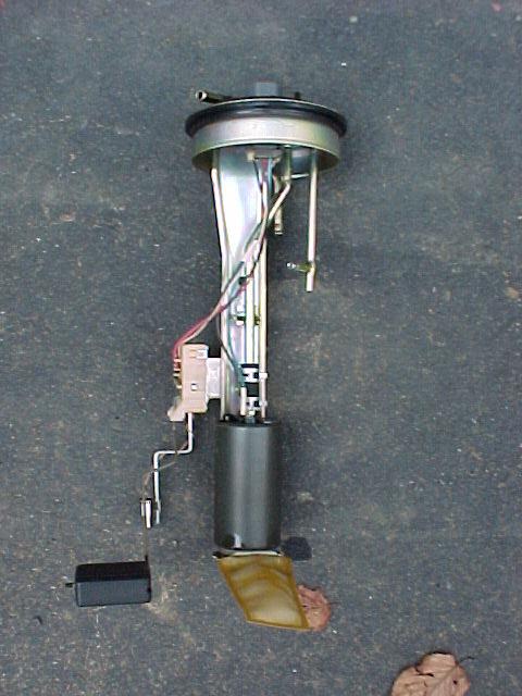
Here is a shot of the dual
Walbro pumps mounted on the intank
hangar. You can see the tee where the two pumps come together, and the
braided line from the tee going to the stock pump outlet.
Different view
“DualPumps”.
A shot of the top of the fuel
pump access hatch showing the banjo
fitting and -6an line going to the rail.
Dual Walbro pumps (note small
pump size), Stock MKIII pump (same
size as MKIV pump), and Python pump (unpainted). The Python pump was
pathetic, I didn’t even include it on the flow chart.
Different view of
“Pumps”
Comments/suggestions? Email
me
![]()
Apu
| new readers rides system!! click here to put in your entry. |
 home
home


Apexi afc install instructions
A’PEXi
S-AFC Installation
Concept:
Entry-level fuel computer designed to modify the air flow meter signal.
Also
can be used instead of the GCC for finer control of your VPC.Characteristics:
Easy to read VFD display, unparalleled list of functions
Comments:
The second generation SUPER AFC follows the highly successful SUPER AFC in an
upgraded package. The SUPER AFC is a vehicle specific fuel computer that
modifies the air flow meter signal/ pressure sensor signal and allows the user
to either richen or lean the fuel mixture. Adjustment ranges from +/- 50%. The
Super AFC boasts an 8-point adjustable fuel curve with 500 RPM increment
setting points. The Super AFC also allows the user to adjust fuel enrichment
according to either LO/HI throttle positions. The AFC also cures the erratic
idle problems associated with open atmosphere blow off valves on hot-wire air
flow meter equipped vehicles. MONITOR MODE shows analog meter faces, Y graph
display, Numerical display, Peak Hold, Replay Mode, 1 point/10 point and ghost
map tracing. All correction factors are also displayed in percentages.
Here is
what you will need:–
S-AFC wiring harness and head
unit–
10mm socket–
Wire crimpers–
Butt connectors
and the supplied connectors
Lets
get started!1.Remove the negative
battery cable.
2.Remove the wiring harness
from the ECU.
3.Refer to the ECU diagram.
- Splice
the Green
Wire (RPM) into 58.- Splice
the Gray
Wire (Throttle) into 43.- Cut
wire 66 in half, leave yourself enough room to connect a wire to ECU harness.- Connect
the Yellow
wire to the 66 wire connected TO the ECU harness.- Connect
the White
wire to the 66 wire heading AWAY from the ECU harness.- Splice
the Brown wire (ground 1) into 69,
close to the ecu.- Splice
the Black wire (ground 2) into 69 at least 1cm away from the Brown
wire.- Splice
the Red wire (12V+) in to ECU wire 31.- Pink
and Orange
wires are not used.OK,
Now you have all of the wiring done, double check all of your
connections, reconnect the wiring harness
to your ECU. Make sure all of
those wires are still tight. Plug the harness into the S-AFC.
Reconnect your battery cable. Turn the ignition to the ON position.
The AFC should boot up and display A’PEXi, if screen did not light
up, stop disconnect the battery and find out what went wrong.
Most likely it is power or ground problem (or a loose ecu harness.)
If the
unit Powers On, follow these steps:First
start off by Resetting the AFC.
Many have often complained that their AFC does not show full
throttle(%100), regardless if
it is brand new. Go under [etc.] and
press NEXT~>. Confirm “YES” when prompted “Init.
All?” and
press NEXT again, Now turn the ignition OFF and then back ON, and the unit
should now be reset and ready.Next
enter the following basic settings:-Go to [main]
~>[setting] ~> [3. TH-Point] ~>
[Lo-94, Hi-95]-Go to [main] ~>[etc.]
~> [1. Sensor Type] ~> [1.
Hot-Wire] ~> [in-12, Out-12] ~> [in-1, Out-1]-Go to [main] ~>[etc.]
~> [2. Car Select] ~> [Cyl:6, Thr: UP]-Go to [main] ~>[etc.]
~> [3. Graph scale] ~> [Ne = 7000rpm][Ne-POINT = 3500, 4000,
4500, 5000, 5500, 6000, 6500, 7000][Dec. -Air = NOT USED, unless you
want to use it to compensate for venting your BOV to atmosphere]Do not modify the low
throttle settings. While at low throttle (in closed loop mode) the ecu
will counteract any changes made and over time your long term fuel map will be
modified. I recommend modifying your high
throttle fuel curve on the dyno with an air/fuel ratio meter & egt gauge
installed. For maximum power, one
probably wants to run an air to fuel ratio of between 11:1 (rich) and 12.5:1
(lean) Do
yourself a favor and pay a professional to tune it. If you lean your
engine out, things can melt.
Blue wire
mod info:
This allows you to read Oxygen
Sensor Voltage on the AFC display. On the wiring harness for the AFC the blue wire
is not normally used. The blue wire is meant for
the second Mass Air Flow Meter on a Nissan 300ZX. You will connect this wire
to the O2 sensor wire right at the ECU.
To read the O2 sensor voltage, scroll down to and select the “etc.”
menu. Select the “Sensor Check”. Of the three readings, O2 voltage
will be the middle one (#2).
VPC+AFC
If you are installing the VPC with
the AFC, then install the AFC on the output wire of VPC
![]()
Greddy e-manage fuel controller install
E-manage Install
on 1993-1998 Supra Twin Turbo
Shortcuts:
-
(1) –
Installing the MAF, RPM, Throttle, Power & Ground Wires -
(2) –
Installing the
Injector Wires into the E-manage
Main Harness -
(3) –
Installing the E-manage Injector Wires into the
ECU Harness -
(4) –
Installing the Ignition Wires into the E-manage Ignition
Harness -
(5) –
Installing the E-manage Ignition Wires into the
ECU Harness
(1)
–
Installing the MAF, RPM, Throttle, Power & Ground Wires
1. Remove the negative
battery cable.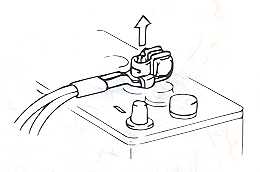
2. Remove the wiring harness
from the ECU.

3. Refer to the ECU diagram.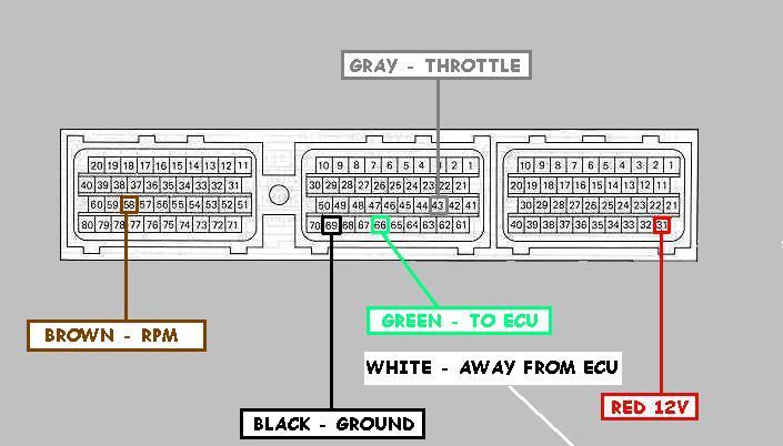
-
Splice the
BROWN
Wire (RPM) into 58. -
Splice the
Gray
Wire (Throttle) into 43. -
Cut wire 66 in half,
leave yourself enough room to connect a wire to ECU harness. -
Connect the
GREEN
wire to the 66 wire connected TO the ECU harness. -
Connect the
White
wire to the 66 wire heading AWAY from the ECU harness. -
Splice the
Black
wire (Ground) into 69. -
Splice the
Red wire (12V+) in to wire 31.
OK, Now you have all of the
main wiring
done, double check all of your connections,
reconnect the wiring harness to your ECU. Make
sure all of those wires are still tight.
Reconnect your negative battery cable. Turn the ignition to the ON position. The
E-manage
should light up.
(2) –
Installing the
Injector & Sub-Injector Wires into the E-manage
Main Harness
-
Install the injector wires into the
main harness as shown below.
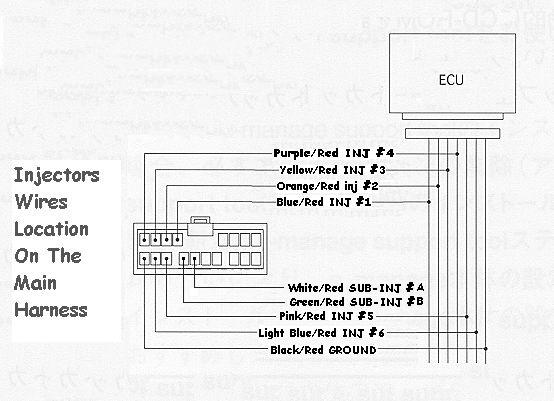
-
It should look like this in the
end (without the Sub-Injector wires),


-
It should look like this in the
end (with the Sub-Injector wires),


(3) –
Installing the
E-manage Injector Wires into the
ECU Harness
1. Remove the negative
battery cable.
2. Remove the wiring harness
from the ECU.
3. Refer to the ECU diagram below.
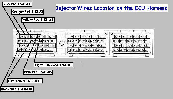
-
Splice the
BLUE/Red
(INJ#1) into 20. -
Splice the
Orange/Red
Wire (INJ#2) into 19. -
Splice the
Yellow/Red
Wire (INJ#3) into 18. -
Splice the
Purple/Red
Wire (INJ#4) into 17. -
Splice the
Pink/Red
Wire (INJ#5) into 16. -
Splice the
Light Blue/Red
Wire (INJ#6) into 15. - Splice the
Black/Red
wire (INJ Ground) into 80.
(4) –
Installing the
Ignition Wires into the E-manage Ignition
Harness
-
Install the ignition wires into the
main harness as shown below.
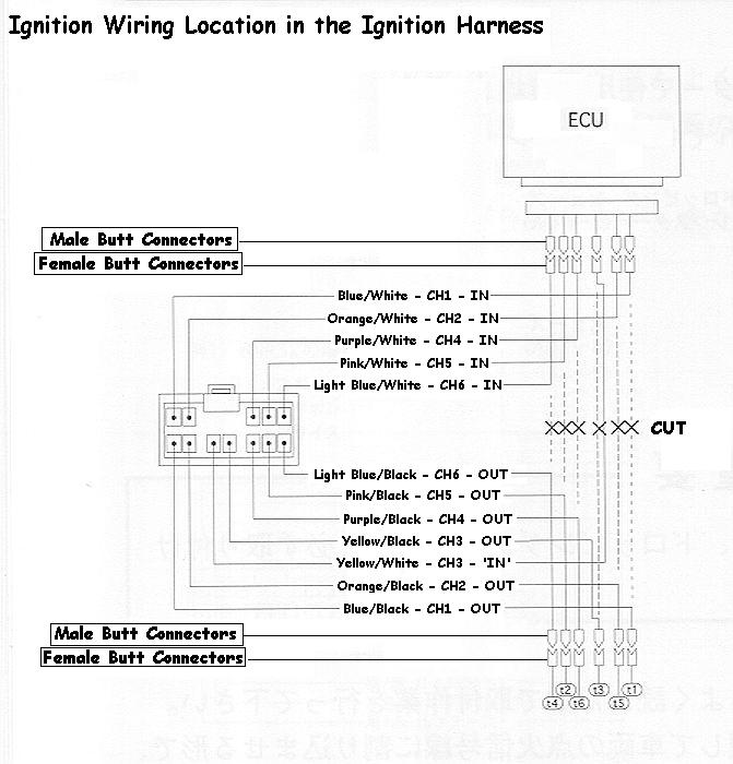
- It should look like this in the end,


- Install FEMALE BUTT connectors on ALL the WHITE
marked wires. - Install MALE BUTT connectors on ALL the BLACK
marked wires.


(5) –
Installing the
E-manage Ignition Wires into the
ECU Harness
1.Remove the negative
battery cable.
2.Remove the wiring harness
from the ECU.
3.Refer to the ECU diagram below.
- Cut wires 57,56,55,54,53,52 on the ECU harness.
- Install MALE BUTT connectors on ALL the wires
coming from the ECU harness. - Install FEMALE BUTT connectors on ALL the
wires that been cut away from the ECU. - Start plugging the Male Connectors into the Female
as shown in step
4 above.
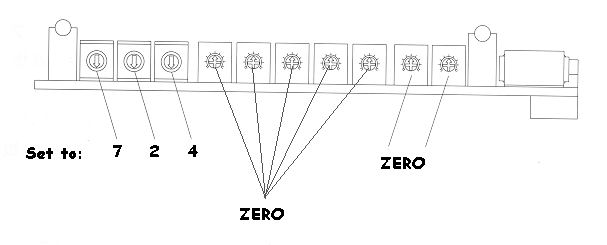
(6) – Setting the Knobs
inside the E-manage
- Remove the E-manage circuit bored from the E-manage
box,
- Take off the 4 Allen screws from the front panel
with the Allen tool supplied. - Remove two bottom Philip screws.

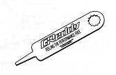
- Using the supplied Greddy tool, Set the knobs on the Left to 7,2,4, and the rest to
zero’s. - 7 = Direct ignition
- 2 = Hotwire
- 4 = Toyota Hotwire
TY_HW-5 (Toyota Hotwire Type-5)
(7) – Jumper Setting

Here are all the wires installed on the
Field’s
Harness (If you are using one).


![]()
Bpu++
| new readers rides system!! click here to put in your entry. |
|
|||||||||||||||||||||||||||||||||||||||||||||||||||||||||||||||||||||||||||||||||||||||||||||||||||||||||||||||||||||||||||||||||||||||||||||||||||||||||||||||||||||||||||||||||||||||||||||||||||||||||||||||||||||||||||||||||||||||||||||||||||||||||||||||||||||||||||||||||||||||||||||||||||||||||||||||||||||||||||||||||||||||||||||||||||||||||||||||||||||||||||
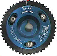
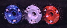
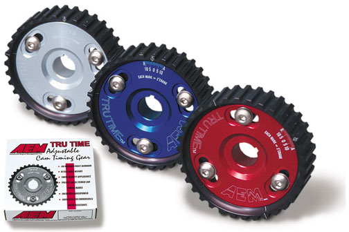
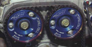
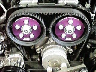
Adjustable cam gears photos
Adjustable Cam
Gears
|
AEM Cam |
|
|
|
|
|
|
|

|

|
|
|
“aem.jpg”> |
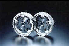
| HKS Cam Gears | |
|
|
|
|
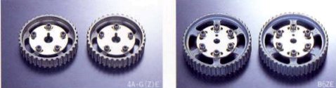
Unorthodox |
|
|
|
|


![]()