
Category Archives: BPU++
Other mods
| new readers rides system!! click here to put in your entry. |
 home
home


Vpc install instructions
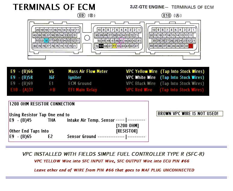
HKS VPC Install Instructions
How
to Hard Wire the HKS VPC?
Note:
This tech tip focuses on the basic install of the vpc & not tuning.
Tools/Parts
Required:
Phillips screwdriver, sildenafil 12mm socket wrench, Needle nose
pliers, 10mm & 12mm flat wrench, Some zip ties, a small T, & a razor.
Steps
:
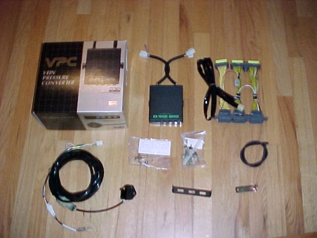
Here is everything that comes w/ the VPC – spent $950 w/
single turbo prom.
The stock MAF (Mass Air Flow) Sensor will be removed. Put
electrical
tape on the connector for the MAF & secure it
somewhere. It will no longer
be used. If you dont know where the MAF is, then you shouldnt be doing this mod!
You need to remove the scuff plate on the passengers side,
one black
snap (on the scuff plate), two phillips head snaps holding
the carpet down
on the kickboard. Remove the kickboard using a 12 socket
(2) 12mm nuts.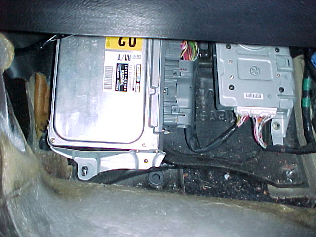
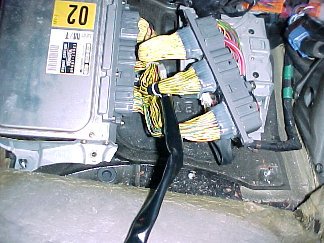
Disconnect the wiring
from the ecu, plug the vpc harness in…cake
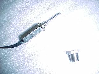
This is the vpc temperature probe
This is the stock gas filter, we need to remove it &
place the
temp probe here – its right next/below to the turbo
pressure sensor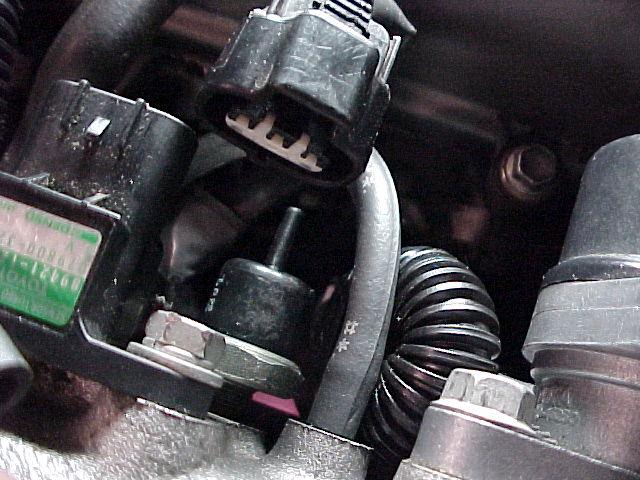
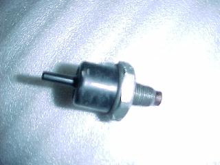
Here is the stock gas filter removed from the intake
manifold
This fitting replaces the gas filter. Screws right in w/ no
problems.
See the vaccum hose next to the fitting – this vaccum hose
will be
disconnected, pull the hose from under the intake manifold,
it will
later be used in a T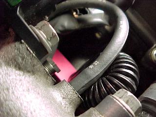
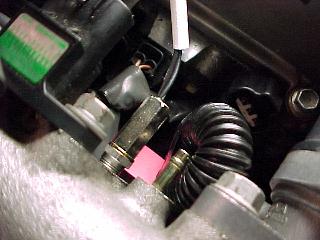
Now screw in the temp probe
The vaccum hose that used to be on the temp probe is out of
the picture, the nipple next to the temp probe will go to a
T
explained in the pic below. The other end is explained in
the
pic after the next.
The vaccum hose from the power steering is disconnected,
this is
where our pressure sensor will be plumbed to. The power
steering
vaccum hose (just disconnected from the nipple on the
intake manifold)
will go to a T. The other end of the T will be run up the
intake manifold
to the white T pictured earlier. Remember the hose we
disconnected next
to the temperature sensor? This hose is connected to the
3rd part of the T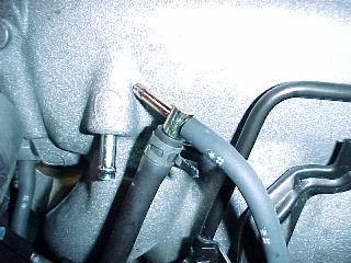
Here is a closeup of the vaccum hoses by the temp sensor.
Your vaccum hoses to the left of the T may have a different
arrangement because my EVC pressure sensor & HKS BOV
are plumbed to the stock T (far left) – so if your setup
looks
different left of the white T – dont worry about it.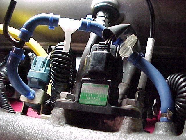
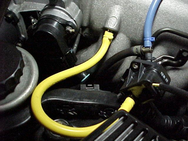
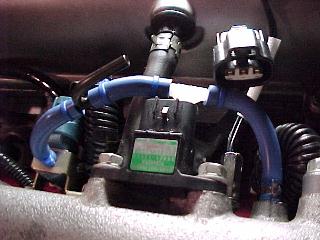
Here is the turbo pressure sensor connected to where the
power steering
vaccum previously resided (yellow hose). See the T? The
hose pointing
left is the power steering vaccum hose, the blue hose
pointing up is going
to the white T pictured earlier. The black vaccum
hose pointing down
is the hose off the nipple next to the temp probe. Did that
make sense?
Read it a couple times slowly 🙂
*The
1200 ohm resistor can be also connected from the MAF harness, much easier to
install that way.
VPC unit
Inside look
Dip Switches for the MKIV
VPC Prom for auto (AT), Stock
injectors


Fuel system upgrade with 720 injectors
Fuel System Upgrade
Instructions
Big Thanks to Bryce Danna & Bruce St.
John
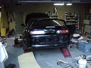
Ok, so I decided to go with a single turbo setup….now my
worry at the time was fuel…..I dont want to ever worry about running out, so I’ve
decided to upgrade the whole fuel system in my Supra.
Disclaimer: This page is for information purposes only, by viewing this web page you
agree that I am no way responsible for you screwing up your car!
Note:
This tech tip focuses on the basic install fuel system upgrade instructions.
Tools required
: You will need a good set of tools, mostly you
will be using 10, 12, & 14mm sockets & flat wrenches, screw drivers (phillips
& flat), hammer, etc, etc
Steps
:
![]()
Here is everything you need for this bad ass
fuel system
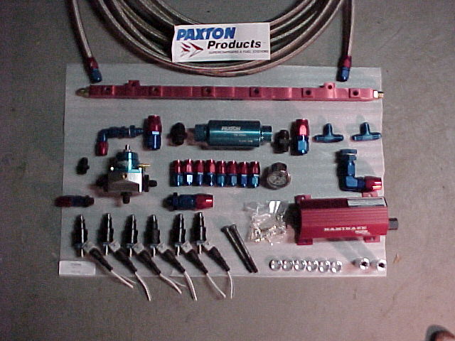
- (6) 720 cc injectors
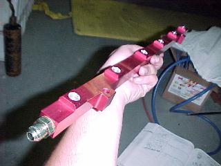
- HKS Fuel Rail
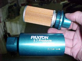
- Paxton Inline fuel filter for turbo cars
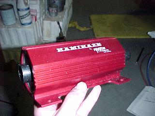
- Paxton Kamakaze 750 Fuel pump
- 4ft of -10 AN highpressure hose
- 15ft of -6 AN highpressure hose
- (2) -6 X -6 X -6 AN T’s
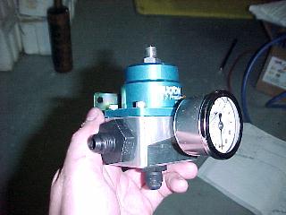
- Paxton Fuel Pressure Regulator w/ gauge
- HKS VPC (prom for 720cc injectors) – look at my page for
instructions on this - Lots of patience if your going to do this yourself!!
-
If you have the Toyota Supra repair manual,
that will help alot too!
For any bolts you cant break loose, definetly
get a can of this stuff….
Your also going to have to jack the car up on
all 4’s….or get it on a lift….
Here is an over view of the installation….

![]()
Here is how this is going to work,
We are going to drill a hole in the bottom of
the tank & run a -10 to the fuel filter….
![]()
From the filter we run a -10 to the fuel
pump….
![]()
Now picture the rail with 1 1/2ft of -6 from
one end of the rail to the other….
![]()
On this loop we are going to have TWO T’s (-6
X -6 X -6)
On one T is going to be the -6 feed from the
pump,
on the other T is going to be the FPR (fuel
pressure regulator),
From the bottom of the FPR we run a -6 to the
tank for our fuel return….
![]()
![]()
![]()


![twinturbokit[1].jpg (71394 bytes)](twinturbokit%5B1%5D.jpg)


![image058[1].jpg (96493 bytes)](image058%5B1%5D.jpg)
![imageNGL[1].jpg (97409 bytes)](imageNGL%5B1%5D.jpg)
![imageLFK[1].jpg (98199 bytes)](imageLFK%5B1%5D.jpg)
![imageR3C[1].jpg (58640 bytes)](imageR3C%5B1%5D.jpg)
![imageKRN[1].jpg (93733 bytes)](imageKRN%5B1%5D.jpg)
![imageNPU[1].jpg (63703 bytes)](imageNPU%5B1%5D.jpg)


Hks gt intercooler install photos
HKS GT
INTERCOOLER(IC) INSTALL PHOTOS
HKS GT IC(BACK) vs. APEXI
IC(FRONT)


APEXI IC ready to come off


HKS GT IC


HKS new power steering cooler


Coolant reservoir tank
relocation kit


IC mounting brackets


![]()
Rps turbo kit photos & install
RPS Turbo Kit install on 94 MKIV
By Kevin Goroway
[ SP-60 Kit ]
RPS Kit as supplied by Sound Performance
Note: The
dollar bill didn’t come with the kit… it’s there for size reference. 🙂


Here’s a shot of the HKS manifold just
for comparison.


Plug the water
line seen in the next picture. You may want to tie this whole assembly back as
close to the firewall as possible. Otherwise, the lower hose is dangerously
close to the downpipe when its all finished.
This next shot
shows the upper radiator pipe which I took off and had modified. There are
normally two nipples for water hoses here. They are right smack in the way of
the intake to the turbo. This is a very common problem with the RPS header. It
cost me a whole $40 at a local place. Finding someone who would weld aluminum
wasn’t easy, though.
Connect the oil
return line here:


Connect the oil
feed line here:

Plug the rear oil feed line
here:

Now came the hard part. I tried the
header, and it didn’t fit. It became clear that at least one of the bolt holes
didn’t line up. I’ve since found out that this is common with the RPS header.
You can see Mark, and Roberto trying to solve the problem with my dremel. We
quickly determined that gasoline powered cars would no longer be legal by the
time we would finish it this way… A Home Depot run later, I was the proud
owner of a 1/2 inch drill, and a bit one size bigger than the hole that RPS gave
me. Roberto muscled his way through the one hole that seemed to be the problem.
And, luckily, we were able to get it to clear all of the bolts. Caution: If you
need to do this, be very very careful. It takes quite a bit of force, and the
collectors are very close to the other side of the hole you are
drilling…


Here’s Roberto fiddling with the lower
back bolt. Because of the turn in that rear collector, the bolt basically has to
be threaded on as the header is pushed on…What a PITA.
It’s on! And the EGT probe is
mounted.

It was about now that we realized
that the kit was missing the bolts to connect the oil return line to the turbo.
It was also missing the long bolt for the sorta built-in clamp that is part of
the wastegate/downpipe. A quick run to the hardware store, and you can see it in
the second pic here. Downpipe, and Turbo installed.

Connect the oil feed line, and the oil
return line. Bolt in the primary O2 sensor. And the turbo is done. There is one
more radiator hose to plug. You can see it in the second picture above. It’s the
one right behind the water pump. You may also notice in the first of the two
pics above that my (black) upper intercooler pipe (part of the XS intercooler)
will certainly need to be cut. So, I went and bought one of these. 🙂 I didn’t
want to worry about shavings that would be caused by using a hacksaw, or
anything similar. This pipe cutter was perfect.


It was after this upper intercooler
pipe/blow-off valve combination was installed that I realized I was going to
have to tap into the pipe and install a fitting for a pressure source… I
needed this pressure source for my boost-controller/waste-gate. I wanted the tap
to look neat, so it’s under the pipe, where the blow-off valve is welded
on.
Next was the intake. Notice that I have capped the port in the intake.
This is supposed to take a hose from the port on top of the valve cover, as seen
here . But that will lead to oil in the intake track. Better
to just put a small breather up there.


Here’s a few shots of the inside of
the car. Next to the TRAC button you can see a switch I made for my
two-step.


This is where
the Apexi boost meter is tied up.

Here’s Henri
under the car tieing up my mid-pipe so I can drive the car to an exhaust shop
(loudly) to get a downpipe made for the new turbo.
![]()
Hks gt intercooler install photos
HKS GT
INTERCOOLER(IC) INSTALL PHOTOS
HKS GT IC(BACK) vs. APEXI
IC(FRONT)
APEXI IC ready to come off
HKS GT IC
HKS new power steering cooler
Coolant reservoir tank
relocation kit
IC mounting brackets
![]()


Apu
| new readers rides system!! click here to put in your entry. |
|
|||||||||||||||||||||||||||||||||||||||||||||||||||||||||||||||||||||||||||||||||||||||||||||||||||||||||||||||||||||||||||||||||||||||||||||||||||||||||||||||||||||||||||||||||||||||||||||||||||||||||||||||||||||||||||||||||||||||||||||||||||||||||||||||||||||||||||||||||||||||||||||||||||||||||||||||||||||||||||||||||||||||||||||||||||||||||||||||||||||||||||