Category Archives: Other Mods
Custom built front grill
Custom Built
Front Grill

|
For the grill I made for my car, I used Ceramic Tile underlayment mesh. This silver mesh is a treated aluminized steel that will not rust. You can buy it at Home Depot and such. Tile layers staple it to the floor and then lay tile adhesive on top of it to give it a surface to bite into.
Wear gloves when cutting the mesh with tin snips…its VERY sharp.
Happy grilling! |


![]()
Trd strut brace installation photos & translated instructions
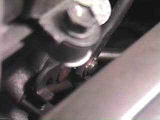
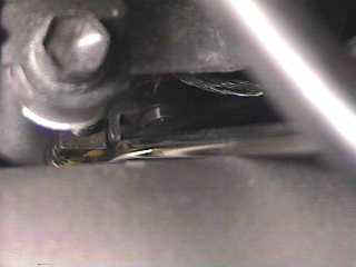
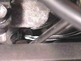
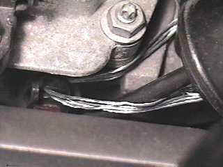
TRD Front Strut Tower Brace
Installation Photos
![strut1-5[1].jpg (67405 bytes)](strut1-5%5B1%5D.jpg)
![strut2-5[1].jpg (57476 bytes)](strut2-5%5B1%5D.jpg)
![strut4-5[1].jpg (66729 bytes)](strut4-5%5B1%5D.jpg)
![strut6-5[1].jpg (65519 bytes)](strut6-5%5B1%5D.jpg)
![strut7-5[1].jpg (58259 bytes)](strut7-5%5B1%5D.jpg)
![strut8-5[1].jpg (68551 bytes)](strut8-5%5B1%5D.jpg)
Brace Translated Instructions
When I received my TRD front strut tower brace,
I was ecstatic. The form and finish was spectacular. But once I checked out the
instruction manual, I knew I was in for quite an adventure, since it was
completely in Japanese !
Luckily I work with someone who is fluent in Japanese. Thanks goes to Hirota-san
for translating this installation manual. It’s not a complete translation, but
all the pertinent stuff is here.
NOTE: Any comments I have added are embedded [in brackets]
below. Please use this as a helpful guideline – there is no guarantee to the
accuracy of this translation, and you must take the full responsibility for your
own installation.
*** PAGE ONE ***
| TRD Racing Development | 53607-JA810 |
| TRD Racing Sporty Driving Parts |
Strut Tower Bar Mounting & Handling Instruction Paper |
Part Numbers and Applicable Models
| Part Number | Type | Model | Year | Notes |
| 53607-JA810 | Supra | JZA80 | All | Turbo ONLY |
Contents
| No. | Item | Quantity | Description |
| 1 | Tower Bar | 1 | “Made with Steel” |
| 2 | Washer | 2 | 0.9mm thick |
| 3 | Washer | 4 | 1.6mm thick |
| 4 | Instructions | 1 | n/a |
[Note, I also received 4 lock washers which I used in
conjunction with Item #3]
Cautions when Installing
|
*** PAGE TWO ***
Mounting Instructions
|
[Special note: My 1997 Supra had an ignitor module mounted
directly on the driver’s side strut tower – this would NOT re-install in it’s
original location once the brace was installed. I solved this by relocating the
ignitor module towards the master brake cylinder side, and attached it to one of
the suspension studs with the existing nut]
Cautions when Installing
|
Toyota Techno Craft, Inc TRD Sales Office Telephone & Fax info
![]()


True twin turbo conversion (ttc) mod
|
True What it does: Why would I want to
What are the Parts Time Note:
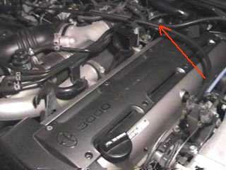
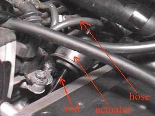
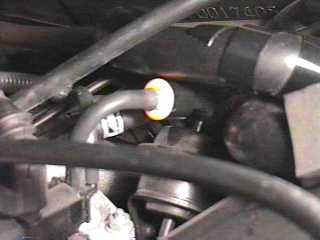
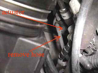
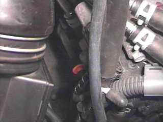
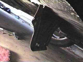
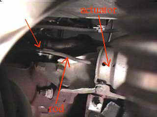
Locate the EGC actuator (about the size of a
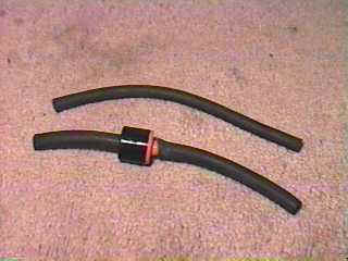
As above, cut the vacuum hose that you
Take the car for a spin. Accelerate moderately If you like the new powerband, you need to
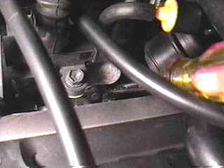
How Top actuator: Use a flat-blade screwdriver to
Here is what the actuator looks like:
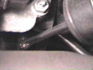
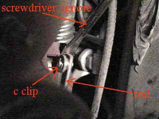
Remove the c clip at the end of the rod by
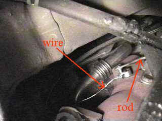
Detach the rod. Tie some wire thru the hole
|
Ettc mod
Electronic-True
Twin Conversion
(E-TTC)By:
Jeff Lee
This page is currently Under
Development and some illustrations may not be available at this time.
Please check back at a later time and sorry for the inconvenience.
- *****IMPORTANT NOTICE*****
- This mod may put
additional stress on your pressure tank, which is used to “lock on” your
actuators during 1st->1st+2nd transition. The tank will be mainly
used in this mod to keep the Intake Air Control Valve (IACV) and Exhaust
Gas Control Valve (EGCV) open during TTC mode. So make sure your
pressure tank is working properly before performing this mod. If
you notice your turbo(s) not properly spooling up after performing this
mod, you may want to replace your pressure tank. (About $35) Perform
this mod at your own risk and make sure that you are knowledgeable with
simple electrical wiring/splicing/soldering and that you have an complete
understanding with the Supra’s vacuum/turbo system routing. So pretty
much: Make sure you know exactly what you are doing!
What this Mod does:
This mod (when done properly)
will enable you to electronically switch, using a simple rocker switch,
from the Supra’s conventional sequential turbo setup to TTC without the
use of check valves nor having to tamper with the hoses. Many have
often complained about the lag associated with TTC (especially on autos),
this mod will eliminate such problems by letting YOU the driver choose
which turbo mode (Seq/TTC) you want your car to run in with a flip of a
switch!
The Concept:
Originally,
the IACV and EGCV actuators are only to be opened by the ECU via VSV’s
at around 4500rpm, thus switching to car to twin turbo mode. The
original “TTC” method works when the IACV and EGCV actuators are forced
open by pressure being trapped inside the actuator itself (pressurized
from the pressure tank), either by using check valves or wiring the actuators
shut. With
these two actuators always open now, the turbos will then spool up simultaneously.
What this mod pretty much does, is simply bypass the ECU’s signal into
the IACV and EGVC VSV’s (which only occurs at ~4500rpm), and substitute
it with a constant GND signal. This will keep the VSV’s always “activated”
and always closed. As the pressure tank then pressurizes the system
under boost, the activated VSV’s will keep the pressure trapped inside
the system, thus keeping the IACV and EGCV actuators open as well.
The output of the pressure tank will function as the “check valve,” for
it only allows pressure out one way when it is built up.
(You may want to place a check valve in front of the pressure tank output,
to prevent probable leakage)
The purpose of this mod is to make a toggle switch between the ECU signal,
and a constant signal into the VSV’s.
Tools/Supplies required:
– Splicing/crimping pliers
– Electrical tape
– Butt-connectors or wire splices
– (SW-1) Dual-latch rocker switch.
(Can be found at radio shack)
– (4) Spools of wire of different
colors,
(24AWG or greater, stranded,
high temp recommended)
– Soldering Iron and Solder
!STOP!
Like performing
any other mod, be sure the negative cable of the battery has been disconnected
before continuing.Step 1:
-Locate the
IACV and EGCV VSV’s, and remove wiring harness.The IACV VSV
is located on top of the 2nd turbo, and the EGCV is located directly behind
the Wastegate Valve VSV.
Hint: For easier
access to the EGCV VSV, you may want to remove the surrounding wire harnesses
(i.e. alternator, wastegate VSV…etc)Step 2 (Refer
to Wiring Schematics):-Identify VSV
wires: (Constant +12v wire and ECU Signal wire)Each VSV contains two
wires. The 1st wire is a Black/Red*
constant +12v signal (for both VSV’s) when the ignition is ON. The
2nd wire is the wire you will need to perform this mod (Green/Yellow
–
EGCV, Green/Blue
–
IACV)*, these are the wires which put out a GND signal from the ECU during
transition to activate the VSV(s). What you need to do is locate
these 2 wires: Green/Yellow
for EGCV VSV, and Green/Blue
for IACV VSV.* = This mod was
performed on my `94 Supra (should be same for `93-`96). Wire colors may
vary on different cars depending on production date, check with your service
manual (or Mohd) if you have a later model for the correct wire color.
CLICK
HERE TO VIEW WIRING SCHEMATICS
Step 3 (Refer
to Wiring Schematics):-EGCV VSV: Cut
(yes i know…sorry) the Green/Yellow
ECU wire, leaving at least 1-1/2″ of wire off from the harness to have
enough of it left so you can crimp or put back to stock at a later time.-IACV VSV: Do
the same as you did for the EGCV VSV, but with the Green/Blue
wire.
Step 4:
-Crimp and extend
cut wires through firewall and into the dash.
Using the wire crimper
and butt-connectors, crimp and extend each of the cut ends of the wires
into the dash. Make sure you know “which wire is which” when
doing this, use different color wire for each. You should have a
total of FOUR wires going into the car (all
properly identified with correpsonding colors: EGCV To-ECU, EGCV
To-VSV, IACV To-ECU, and IACV To-VSV).
These wires will later be used to wire up the e-TTC switch. Familiar
yourself with these four wires! (Pics
not available yet)
Step 5:-Follow the wiring
instructions for “SW-1” as described in the wiring
schematics.
Using a soldering iron, solder the wires
onto SW-1 accordingly. I would recommend also using Heat-Shrink tubing
or electrical tape to insulate the leads. Be sure the IACV wires
are on one side of the switch, and the EGCV wires are on the other as shown
in the diagram. Find a good grounding post on the chassis to make
a ground for the switch (SW-1). When the switch is flipped upwards,
the car should be in Sequential Mode, and TTC when flipped downwards.
(Assuming that you’ve done everything right)Step 6:
-Find a location
to mount SW-1.I mounted mines
next to the TRACTION switch for easy access. (Pics
not available yet)Step 7:
-Finishing up
Double check your
wiring to ensure that it’s correct. After you’ve checked and rechecked,
use electrical tape and/or flex tubing to clean up the wires under the
hood. (Meaning, organizing them to make them look neat) Make sure
the wires will not come into contact with extremely hot surfaces or moving
objects (Watch out especially for the EGCV wires) Now reconnect the
negative battery cable, and ENJOY! 🙂
Using E-TTC (From SEQ to
TTC):During Idle: When the car idling, you
can be able to switch to TTC by flipping the E-TTC switch. After that,
run the car to build up some boost to pressurize the pressure tank. Once
proper pressure is achieved inside the tank, the actuators will then open,
engaging the car in TTC mode.While in Motion: It is *not*
recommended that you attempt to switch to TTC mode when both turbos are not
online, for this will “kick-start” the 2nd turbo if the EBV is not
open yet. In order to engage the car in TTC while the car is in motion,
rev the car up to at least 4500rpm, allowing both 1st and 2nd turbo to be
active, then flip the E-TTC switch. This will “Lock-In” the
turbos, and thus keep the car in parallel TTC mode immediately.
Using E-TTC (From TTC to
SEQ):During Idle or While in Motion: You
can switch back to Sequential mode at any time, as long as the car is not
under boost. Let of the throttle for a bit, and flip the E-TTC switch to
switch back to Sequential mode. (I also do this while cruising next to a
cop, which turns my exhaust sound from a loud “growl”… to a soft
“Lexus-like” sound. TTC —> SEQ 🙂 )
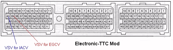
FOR ADVANCED
USERS WITH FIELDS HARNESS:
You may be able to perform
this mod at the ECU using Terminals 39 and 40 (as
shown in schematics). #39 is the EGCV wire, and #40 is the IACV VSV
wire.
Questions? Comments? E-Mail
Me

Indiglo gauge Install
1993-1998 Toyota Supra Indiglo Gauge
Install Procedures
By Larry Ma***More
Photos***I ordered my indiglo gauges from www.Procarparts.com.
This is the 5 color Indiglo gauges that are white in daylight. I’ve try to take
the best pic of each step to help all you other Supra owners who have bought
this kit. The install is fairly simple, just takes some time to make it nice and
neat. Here are the steps I took to install mine:Disclaimer:
These are the steps that I took to
install my Indiglo gauges. Depending on what kit you purchased, results or
install directions may vary. Please read this tech article thoroughly before
starting your install. As usual with any tech article: If you mess up, it’s not
my fault… So be careful.Note: Before you start installing the gauges, you might
want to hook it up to a 12v or 14v source to verify the gauges work before
installing. This will take care of lots of headache later if for a reason they
are not in working order.
Things
needed:
Phillips screwdriver (magnetic tip
preferred)Double-sided tape
Electrical tape/wire
splicersSmall Clippers
1. Disconnect Negative cable to battery, Unscrew Shift-knob from
shifter and remove ashtray from center console.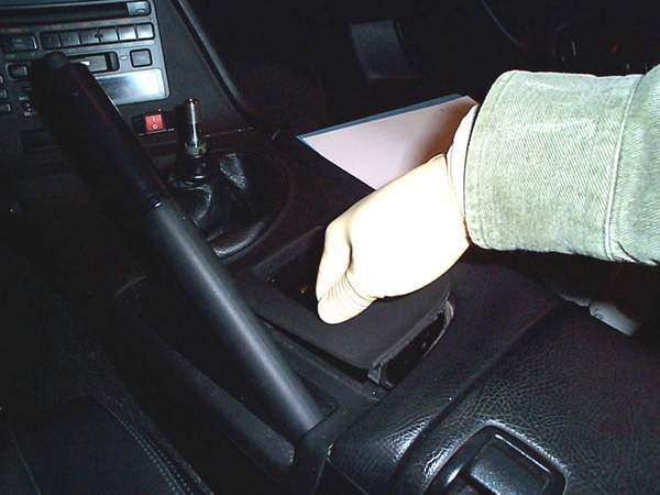
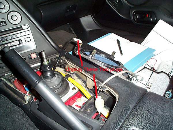
Remove Center Console piece (just pull up as in picture), and
disconnect 2 plugs attached to center panel:
Unscrew 5 Phillips screws from the top instrument panel, pull off
and disconnect 3 plugs from back of panel:
Unscrew screw near top of center console panel (do not drop screw):
And pop off center console and disconnect plugs from back of
panel:
Snap off and remove center gauge panel:
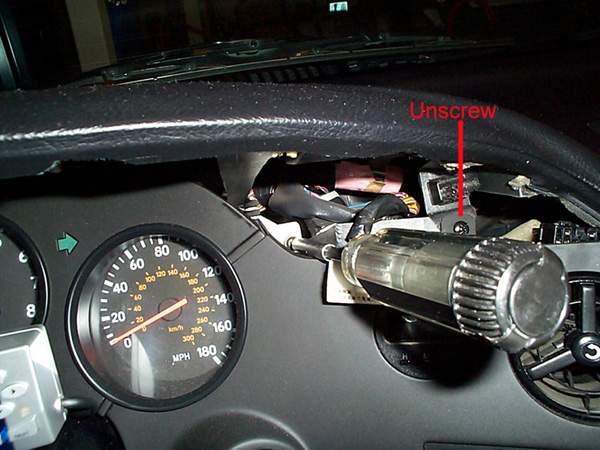
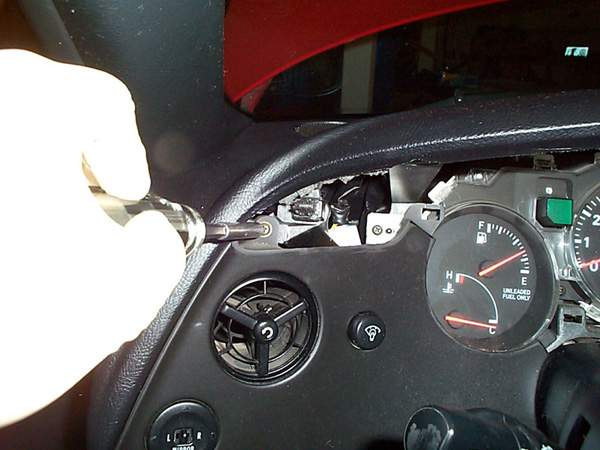
Unscrew screw located top-left on Left dash panel, pull off and
unplug 2 plugs:
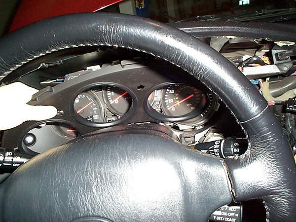
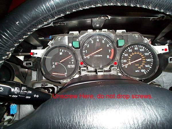
Unscrew 4 screws from gauge cluster:
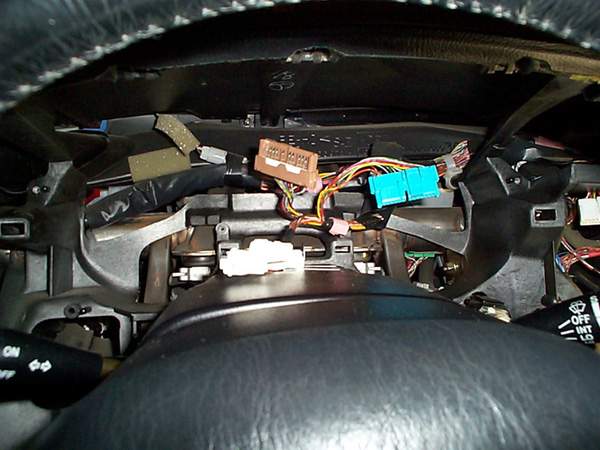
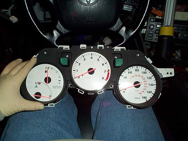
Unplug 3 plugs from back of gauge cluster and remove, this is what
it should look like afterwards:
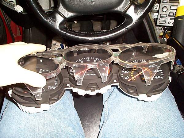
Unsnap all surrounding clips on clear gauge guards and remove clear
cover (be very very careful not to crack the clear guard):
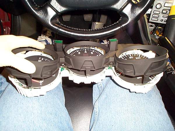
Unsnap all surrounding snaps to black gauge cluster panel and remove
(again, be very careful not to crack it):
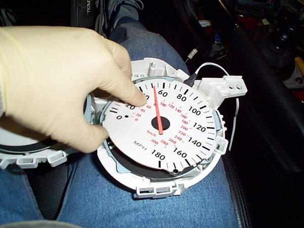
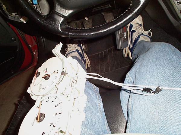
Now you should have just the gauge and needles exposed. Slide the
Gauge faces over the needles, DO NOT remove the
needles or else you will have a heck of a time calibrating it later. I put
double-sided tape under the gauge faces to stick to the stock faces, this
way I could still go back to stock if I choose to later.
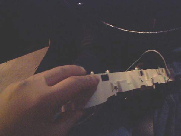
Cut the slits on top left of the cluster enclosure for the wire
connectors to run through:
Run Wire connectors from gauge faces through the hole you just
created in step 12 (kind of a back picture, but you could get the idea of
where the wires are coming out of the little hole:
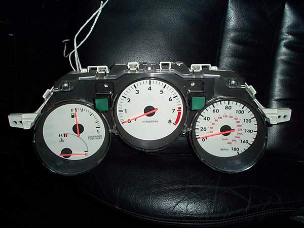
Snap Black Cluster piece back on. This is what it should look like
(be careful not to crack it):
Snap Clear Gauge guard piece back on (be careful not to crack
it):
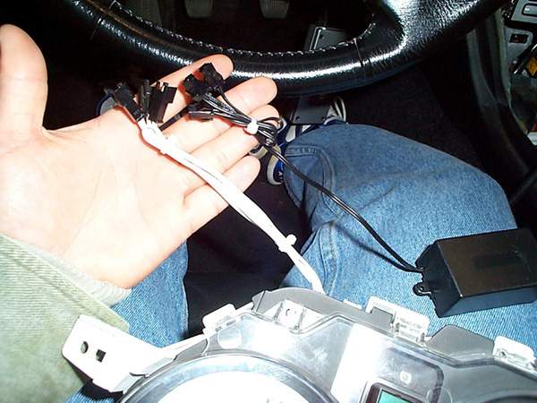
Use small zip-tie to make the wires shorter and neater:
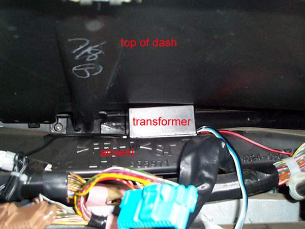
Put some strong double-sided foam tape on bottom of transformer and
mount between bottom of dashcover and air-vent pipe (this will secure the
transformer in place):
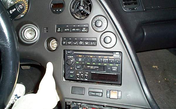
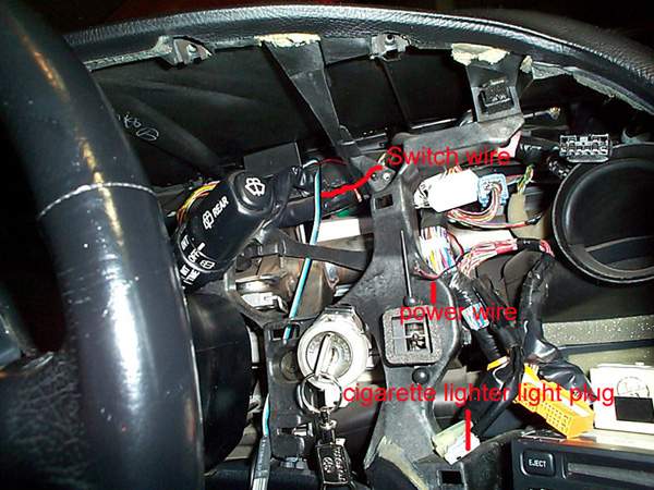
Run Switch wire down by ignition (you could run it anywhere you
want, but I find it more convenient by the ignition), and run the
power/ground wire to center dash (this will tap into power of cigarette
lighter light:
Connect positive (red) of power to “green/yellow” wire and Ground
(black) to “green/white” wire of cigarette lighter light plug. These are
the colors for my ’94 TT, others might be different.(See pic on step 18).
Note: Do NOT tap power for transformer into the stereo
illumination wire, it may induce unwanted high pitch noise from
transformer.
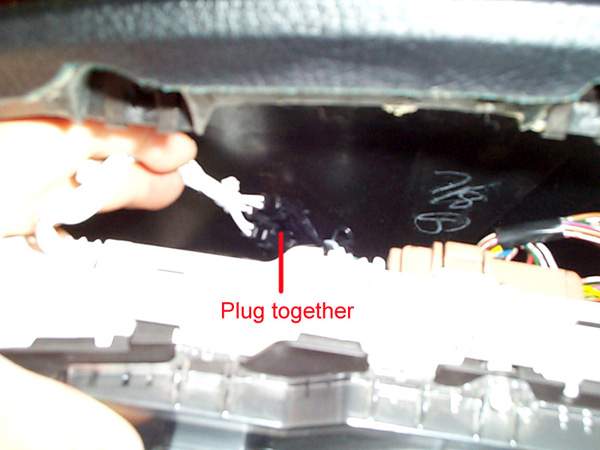
Connect the 3 gauge cluster plugs to the transformer:
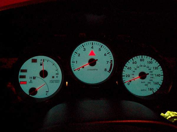
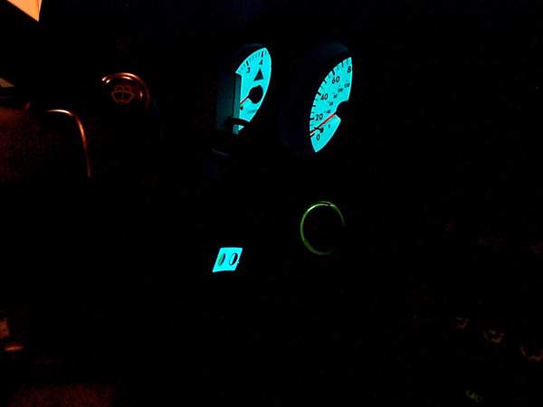
The hard part is complete,now test it to make sure it works before
installing all the panels. You’ll have to plug the dimmer switch in and
turn on your lights, it should light up and you’ll be able to change
colors with the switch. This is what mine looked like:
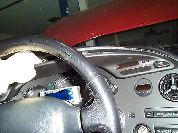
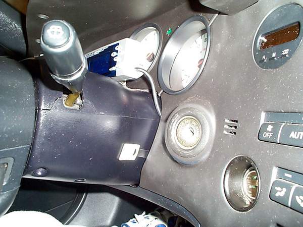
Now Mount the switch on the side of the steering column or wherever
you prefer and install all the panels in reverse order:
Here is a pic of where my switch is mounted with all the panels back
in place:
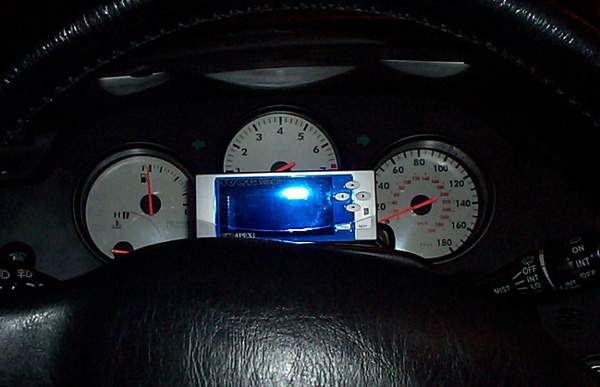
Here is a pic of the switch lit:
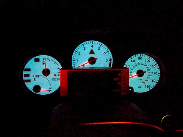
Pics:
OFF:
ON:
THE END!
E-mail me if there are any questions at:
mailto:larryma@larryma.com?Subject=Indiglo
Gauge Install