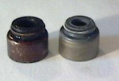
Old & New Seals
Disclaimer: Attempt this job only at your own
risk. Potential risks of this job include (but are not limited
to):
- Dropping valves into cylinders
- Dropping keepers into oil passages (which may
require head removal), (or loosing them if they go flying across your
garage)
- Scratching and/or bending valves
- Putting the wrong valve stem seal onto the wrong
side (eg. intake seal onto exhaust side)…they’re two different part
numbers
- Not getting the seal properly seated – it will then
slip up onto the valve stem and oil will leak (this will be like having
no seal in at all)
- Misshaping the seal when it is pushed into place –
this will also cause a leak
- Forcing or tapping the seal down too hard.
The metal shell of the keeper, forced down too hard onto the top of the
valve guide, can partially or completely cut through the rubber section
at the top of the valve stem seal
Tools Required:
- Toyota Supra Repair Manuals
- Deep 10mm socket
- Big hammer (~4lb)
- Dead-blow (plastic/rubber) hammer
- 8′ of 5/16″ nylon or polyester rope, with a knot
tied at one end
- A 2’x3/16″ aluminum rod
- Valve Stem Seal tool (NB: Needle-nose pliers do not
work),
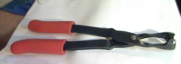 - Seal Removal
Pliers
Keeper
Tools:
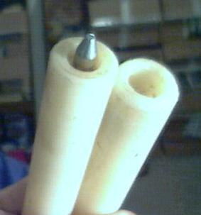
- Pictured to the right is a hand-made pair of
keeper tools. The tool on the left in the picture is for
keeper insertion and can be either made, or purchased (see
below).
- The tool on the right is for keeper removal,
and is relatively easy to fabricate. Simply use a
high-density plastic (preferred) or a hardwood dowel, drill a big
hole in the end, a smaller hole inside that one, and epoxy a
strong magnet into the small hole.
Here is a link
where I believe you can obtain some of the UHD/UHMD Plastic
Rod/Dowel that is used in the valve stem seal tools in the
picture. A 1″ dowel/rod should work well.
- The removal tool’s inner diameter should be
as large as possible, while still keeping a strong shell on the
outside to take the force. I’d estimate that the inner ‘hole’
should be about 5/8″, which would allow for a 3/16″ wall to push
the retainer down with. If you wanted to be really safe, drill a
1/2″ hole and then the wall will be a full 1/4″ thick – the
problem is there might not be enough clearance for the keepers to
pop out of the valve with a 1/2″ hole…
- Place the magnet about 1/2″ to 3/4″ deep. The
depth has to be enough so that the magnet never hits the top of
the valve, no matter how much you compress the valve spring while
pushing on the retainer. The magnet also can’t be too deep or the
magnet will not be strong enough to ‘catch’ the keepers most of
the time
- This Snap-On
tool (pictured on the right) will work for keeper insertion,
but only if it is modified so that it doesn’t scratch the bucket
bores
- This tool is modified by taking a large file
and filing the knurl on the end completely smooth so that it
doesn’t scratch the bucket bores
|
 Keeper Removal Keeper Removal
Tool (on right)
Keeper Insertion
Tool
Other Stuff:
- New keepers, gaskets, etc. from Toyota
- Exhaust: 90913-02088
- Intake: 90913-02106
- I’d recommend you replace the camshaft seals, the
valve cover seals, and possibly the pcv, pcv hoses and valve cover
bolt seal washers. You also might want to change your plugs
since they have to come out anyway.
- Redline Assembly
Lube
- Toyota Form in Place Gasket material (FIPG)
- If this is your first time, consider ordering a few
extra seals of each type, and a few extra keepers (just in case)
- Lots and lots of patience, and at least 10 hours
nonstop
Prep:
- Remove the two engine lift hooks from the
head
- Remove cam covers, camshafts, and spark plugs
according to Toyota Supra Repair Manual
- Note that you should measure the shim
clearance before removing the cams. If any are out of spec,
they can be replaced at the end of the install
- Remove all of the buckets and shims, keeping
them in order (do not mix them up – this is
critical!)
|
|
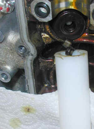
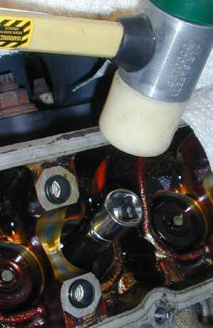
Step1:
- Set the piston in cylinder#1 to BDC (Bottom
Dead Center). You can put the aluminum rod into the
sparkplug hole and watch it while another person turns the
crankshaft with a 22mm socket & ratchet to find BDC.
Mark the depth of BDC on the aluminum rod for reference on the
other cylinders.
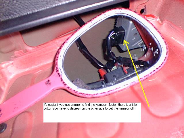
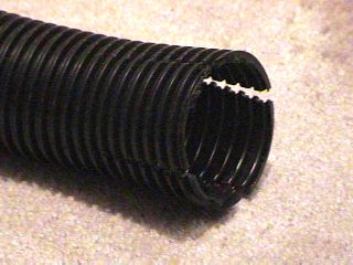
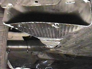
- Using the other aluminum rod (sharpening the
tip a bit helps), stuff all 8′ of the nylon rope into the cylinder
(as in the pic below), and then move the piston towards TDC (top
dead center), until you feel the piston firmly compressing the
rope against the head & the bottom of the valves. The
pic below shows cylinder #2 with the rope, but I’d recommend you
start with #1, just to stay organized. ☻
- Note: In the diagrams, we’re working on the
valve circled in yellow in the pic below.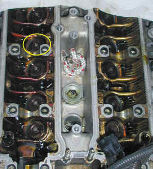
|
|
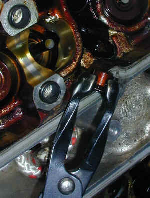
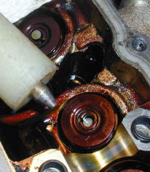
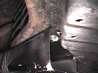
Step 2:
- Put the Keeper Removal tool on top of the
retainer, and give the top of the tool a light blow with the big
hammer. The keepers will pop right out and stick to the
magnet inside of the tool, as shown
|
|
Step3:
- Remove the spring&retainer, reach in with
the seal removal pliers and remove the seal. Again, don’t
try this with needle-nose pliers: when (not if) the pliers slip
off the seal, they will scratch the valve stem. The
intake-side seals are often on so hard that they are very, very
difficult to remove, even with these special
pliers.
- After removing the seal, inspect the base of
where the seal was installed. Often (especially on the
exhaust side), a ring of rubber from inside the old seal will
break off, and you’ll need to use your aluminum rod to remove this
debris.
|
|
Step 4;
- Coat the inside of the new valve stem seal
with
Redline
assembly lube, and with your fingers or the seal pliers, place
the new valve stem seal (make sure you put intake seals onto the
intake side and exhaust seals onto the exhaust side) over the top
of the valve stem, onto the top of the valve guide (as in the pic
to the right). Gently, and then gradually more firmly push
the seal down with 10mm deep socket until it kind of
‘double-clicks’ into place. Be sure you’re pushing the seal
down as squarely/centered as possible so the seal seats properly
and so the valve stem doesn’t get scratched.
|
|
Step 5:
- With the deep 10mm socket over the valve
stem, centered on the top of the seal. Give two light, but
firm blows with the dead-blow hammer. Careful – if you hit
too hard, it will misshape the valve stem seal, or the metal shell
of the seal will cut completely through the seal’s rubber, ruining
the seal. On the other hand, if you don’t hit firmly enough,
the seal might not be properly seated. I estimate about a 2″
‘windup’ and a relatively firm (but not hard) hit.
- As you might guess, this step is the most
critical step in ensuring your new seals will perform
properly. If you suspect a seal may have gotten bent, or the
rubber was damaged in this step, I’d advise to replace the seal
now rather than hoping it will work after reassembly.
|
|
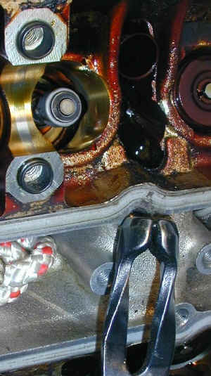
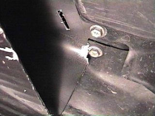
Step 6:
- Replace the spring and retainer, and then
carefully place the 2
keepers into the retainer, above the top of the valve stem, as in
the pic below. Be sure not to drop the keepers – they can
fall into inaccessible crevices, which may require head and/or oil
pan removal.
- Push the keeper insertion tool’s tip in
between the keepers, and push down straight and fairly hard, and
the keepers will pop into place. NB: This technique takes
some practice to perfect. Also, do not hit the keeper insertion
tool with a hammer – your keepers will go flying across your
garage or into your engine.
- If only one keeper gets stuck in and the
other is out, you’ll have to use the keeper removal tool to remove
the one keeper and start this step over.
- After the keepers look like they have been
seated properly, give the top of the valve/retainer a tap with the
plastic hammer to be sure they are locked in place.
|
|
Step 7:
- Repeat steps 2 through 6 on the other 3 valves in
the 1st cylinder, ensuring you use the intake-side valve stem seals on
the intake side, and the exhaust seals on the exhaust side.
- Move the cylinder back to BDC, and remove the
rope.
Step 8:
- Repeat steps 1-7 for the next 5 cylinders (and the
other 20 valves in those cylinders)
Finish:
- Replace all of the buckets and shims, in the same
locations they were removed from.
- Replace camshafts and check shim clearances
according to Toyota Supra Repair Manual.
- Replace the camshaft seals using
Redline assembly
lube on the inside edge of the seals and FIPG on the outside edge of
the seals.
- Replace cam covers using new gaskets and preferably
new sealing washers, along with the sparkplugs, coil packs, etc., all
according to Toyota Supra Repair Manual.
- Replace the two engine lift hooks
Article
feedback
|


 home
home
