
Category Archives: Other Mods
Indiglo gauge Install
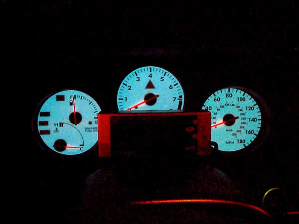
1993-1998 Toyota Supra Indiglo Gauge
Install Procedures
By Larry Ma***More
Photos***I ordered my indiglo gauges from www.Procarparts.com.
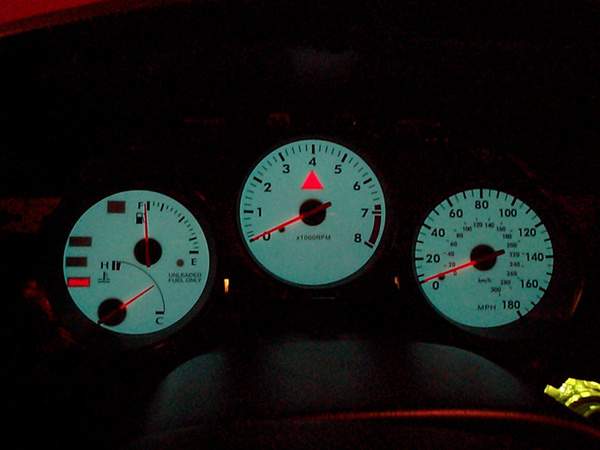
This is the 5 color Indiglo gauges that are white in daylight. I’ve try to take
the best pic of each step to help all you other Supra owners who have bought
this kit. The install is fairly simple, just takes some time to make it nice and
neat. Here are the steps I took to install mine:Disclaimer:
These are the steps that I took to
install my Indiglo gauges. Depending on what kit you purchased, results or
install directions may vary. Please read this tech article thoroughly before
starting your install. As usual with any tech article: If you mess up, it’s not
my fault… So be careful.Note: Before you start installing the gauges, you might
want to hook it up to a 12v or 14v source to verify the gauges work before
installing. This will take care of lots of headache later if for a reason they
are not in working order.
Things
needed:
Phillips screwdriver (magnetic tip
preferred)Double-sided tape
Electrical tape/wire
splicersSmall Clippers
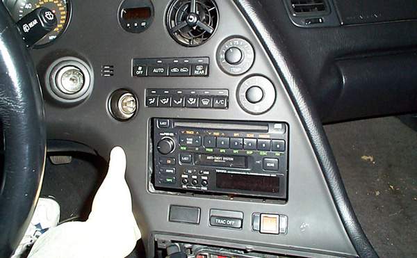
1. Disconnect Negative cable to battery, Unscrew Shift-knob from
shifter and remove ashtray from center console.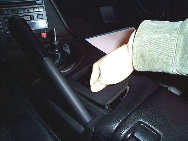
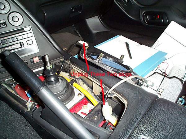
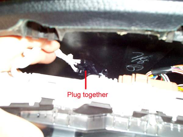
Remove Center Console piece (just pull up as in picture), and
disconnect 2 plugs attached to center panel:
Unscrew 5 Phillips screws from the top instrument panel, pull off
and disconnect 3 plugs from back of panel:
Unscrew screw near top of center console panel (do not drop screw):
And pop off center console and disconnect plugs from back of
panel:
Snap off and remove center gauge panel:
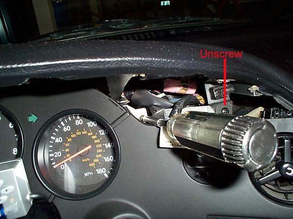
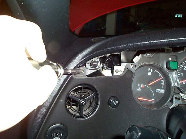
Unscrew screw located top-left on Left dash panel, pull off and
unplug 2 plugs:
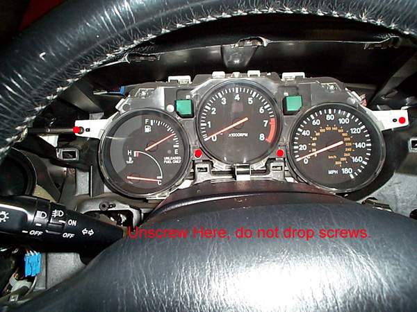
Unscrew 4 screws from gauge cluster:
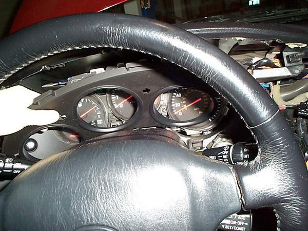
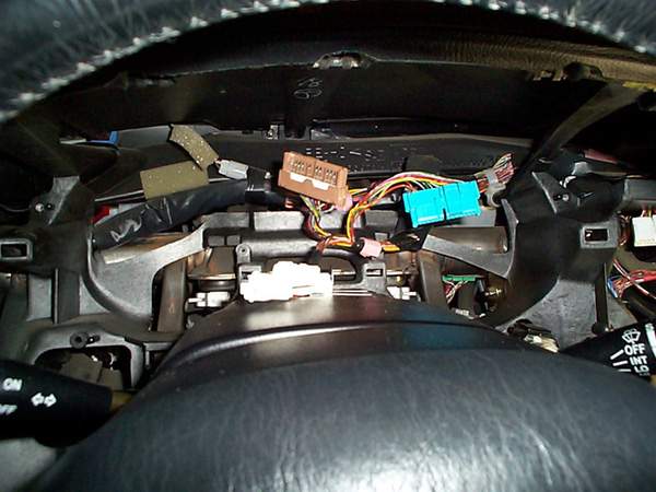
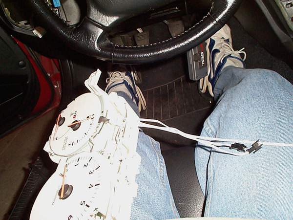
Unplug 3 plugs from back of gauge cluster and remove, this is what
it should look like afterwards:
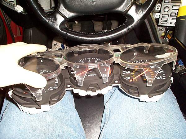
Unsnap all surrounding clips on clear gauge guards and remove clear
cover (be very very careful not to crack the clear guard):
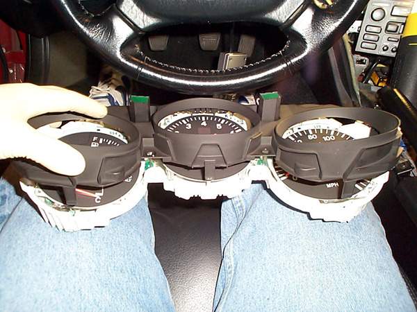
Unsnap all surrounding snaps to black gauge cluster panel and remove
(again, be very careful not to crack it):
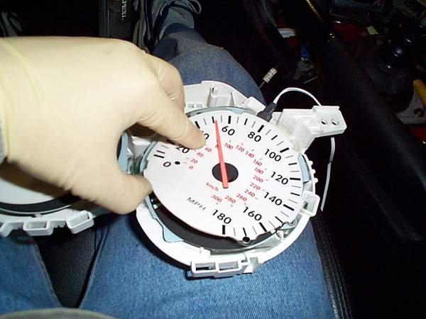
Now you should have just the gauge and needles exposed. Slide the
Gauge faces over the needles, DO NOT remove the
needles or else you will have a heck of a time calibrating it later. I put
double-sided tape under the gauge faces to stick to the stock faces, this
way I could still go back to stock if I choose to later.
Cut the slits on top left of the cluster enclosure for the wire
connectors to run through:
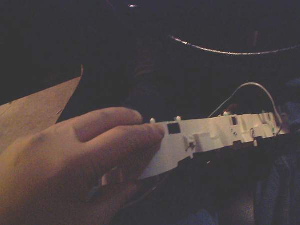
Run Wire connectors from gauge faces through the hole you just
created in step 12 (kind of a back picture, but you could get the idea of
where the wires are coming out of the little hole:
Snap Black Cluster piece back on. This is what it should look like
(be careful not to crack it):
Snap Clear Gauge guard piece back on (be careful not to crack
it):
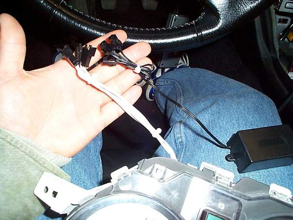
Use small zip-tie to make the wires shorter and neater:
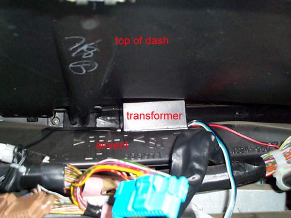
Put some strong double-sided foam tape on bottom of transformer and
mount between bottom of dashcover and air-vent pipe (this will secure the
transformer in place):
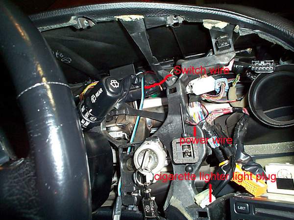
Run Switch wire down by ignition (you could run it anywhere you
want, but I find it more convenient by the ignition), and run the
power/ground wire to center dash (this will tap into power of cigarette
lighter light:
Connect positive (red) of power to “green/yellow” wire and Ground
(black) to “green/white” wire of cigarette lighter light plug. These are
the colors for my ’94 TT, others might be different.(See pic on step 18).
Note: Do NOT tap power for transformer into the stereo
illumination wire, it may induce unwanted high pitch noise from
transformer.
Connect the 3 gauge cluster plugs to the transformer:
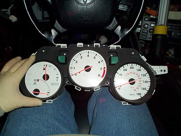
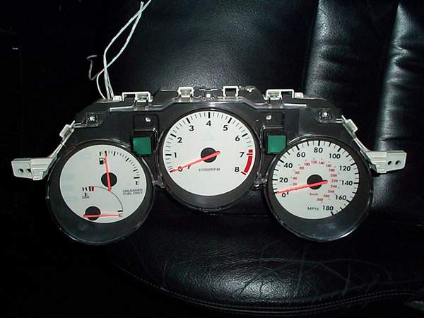
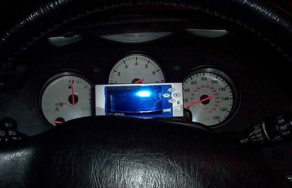
The hard part is complete,now test it to make sure it works before
installing all the panels. You’ll have to plug the dimmer switch in and
turn on your lights, it should light up and you’ll be able to change
colors with the switch. This is what mine looked like:
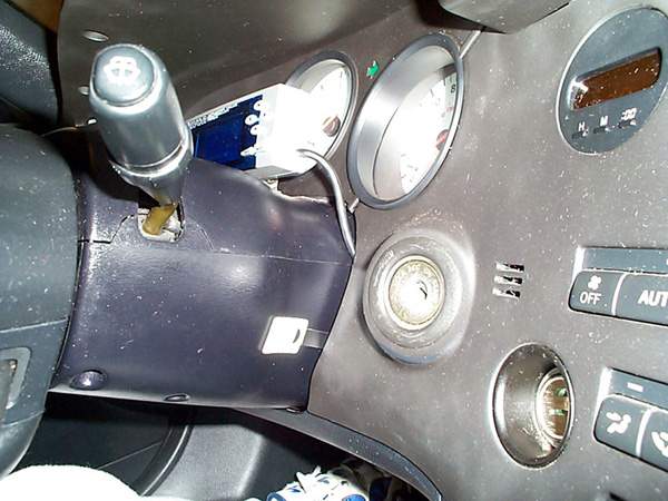
Now Mount the switch on the side of the steering column or wherever
you prefer and install all the panels in reverse order:
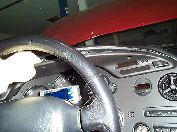
Here is a pic of where my switch is mounted with all the panels back
in place:
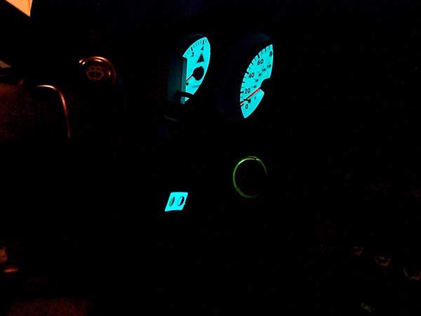
Here is a pic of the switch lit:
Pics:
OFF:
ON:
THE END!
E-mail me if there are any questions at:
mailto:larryma@larryma.com?Subject=Indiglo
Gauge Install
Polishing/cleaning Foggy Supra Headlights
Foggy Supra Headlight Restoration
I’ve helped cleaning out many headlights for local supras down here in SoCal. The discoloration you see
is inside the headlights usally…in some cases outside only. The procedure
requires popping your lights into the oven for about 5 minutes at low temperature
(be careful or you will damage the light), then
removing the plastic casing. From there, you need to polish the plastic with a
good plastic polish and scratch remover. Using the right product is
important, you don’t want to be leaving scratches and nicks on the plastic
surface. Use a product such as Novus, Plexus, or Meguiar’s plastic
cleaner/conditioner. You will certainly want to use Novus, as it will leave the
final surface very clean and shiny. A high speed polisher will save you a
lot of time and effort. Although, it can be done by hand and some elbow
grease.You can also find these at
websites by doing a search for ‘novus plastic cleaner’ or ‘plexus plastic
cleaner.’
Silicone/RTV sealant: can be bought at local car parts stores for about
$3 in a small tube.Sand paper: use 2000Grit paper, and wetsand the outside of the headlights
using a soapy water solution. Your headlights will be crystal clear and
smooth. Also, follow up by buffing the sanded surface with the plastic
polish/cleaner.Oven Temperature: about 175-200F for about 5-10 mins, depending on the
actual temperature of the oven. Leave the headlights in there until they
are somewhat warm to the touch. Start at one end of the headlight, and use
a dull object such as a butter knife of dull screwdriver to separate the
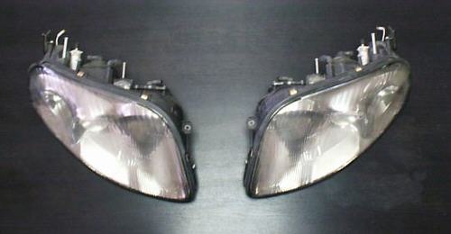
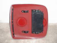
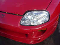
headlights.Here are the headlights we
started with,


Heat the
headlights in the oven, pop ’em apart.
![View[1].jpg (90629 bytes)](View%5B1%5D.jpg)
![View[2].jpg (91869 bytes)](View%5B2%5D.jpg)
Take out the
screw, remove the shiny plastic piece.
![View[3].jpg (89452 bytes)](View%5B3%5D.jpg)
![View[4].jpg (92104 bytes)](View%5B4%5D.jpg)
All three
pieces need cleaning…
![View[5].jpg (90759 bytes)](View%5B5%5D.jpg)
PorterCable
7424, Novus, Plexus, and a Microfiber cloth. Indispensible tools.
![View[6].jpg (89684 bytes)](View%5B6%5D.jpg)
Spray Plexus to
clean the surface. Wipe off with microfiber.
![View[7].jpg (90496 bytes)](View%5B7%5D.jpg)
Apply Novus
heavy scratch remover.
![View[8].jpg (90466 bytes)](View%5B8%5D.jpg)
Buff out
scratches at about 4000rpm.
![View[9].jpg (91761 bytes)](View%5B9%5D.jpg)
Repeat for
outside surface.
Also, wetsand using 2000 grit sandpaper to leave a smooth finish.
![View[10].jpg (90972 bytes)](View%5B10%5D.jpg)
Spray plastic
with Plexus, wipe off.
![View[12].jpg (91257 bytes)](View%5B12%5D.jpg)
![View[13].jpg (89419 bytes)](View%5B13%5D.jpg)
![View[14].jpg (88713 bytes)](View%5B14%5D.jpg)
![View[15].jpg (89311 bytes)](View%5B15%5D.jpg)
The finished
result…clean headlights!
![View[16].jpg (91093 bytes)](View%5B16%5D.jpg)
![View[17].jpg (87232 bytes)](View%5B17%5D.jpg)
Put the screw
back..
![View[18].jpg (90479 bytes)](View%5B18%5D.jpg)
Once the cleaning is done, put
the cleaned two pieces back into
the oven to allow the existing rubber sealant to warm up.
Leave for about 2-3 minutes. Take them out, and apply the
silicone sealant to the two pieces. Put them back together (requires
a bit of force).
Optionally, you can add another bead of silicone sealant once the pieces have
been put back together.
![View[19].jpg (93565 bytes)](View%5B19%5D.jpg)
Here are the headlights after
they were done,

Comments/suggestions? Email
me
![]()
European hood scoop install
European Hood Scoop Install
By Ron Lambertson & Piotr Kapiszewski
Parts List:
76181-14900 Bulge, Hood
76182-14010 Guide, Hood Air Intake
76183-14010 Protector Hood Bulge, No. 1
76184-14010 Protector Hood Bulge, No. 2
76187-14010 Retainer, Hood Air Intake Guide, No. 1 (2)
76192-14010 Plate, Hood Bulge
93567-14512 Screws (8)
90179-06058 Nuts (4)
76186-14010 Seal, Hood Air Intake
Tools:
- Dremel tool and cut off wheels
- four plastic fasteners for the underside metal air guide
- masking tape
- drill and drill bits
- phillips screw driver
- 10 mm scket and ratchet
- razor blade or knife,
- medium grit sand paper
- piece of card board
- panel removing type tool (useful)
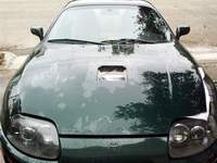
Step by Step:
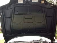
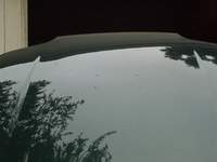
Here is what you are going to start with:
Start at the front of the hood and first take that part out.
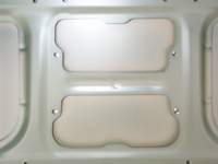
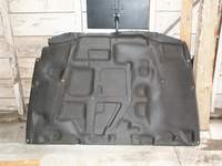
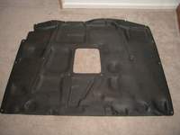
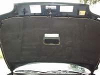
Remove the factory hood heat shield by popping out the
plastic fasteners.
A panel removing tool is helpful. Be
careful not to damage the heat shield.
It’s made of a
paper/fiberglass material that tears easily.
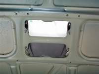
Notice the back two
fasteners don’t pop out.
The just pull up, forward and out of the
holes in the hood.
All others pop out completely.
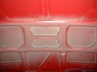
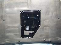
Once you remove the heat shield your hood will look something like
this.
Using a drill bit of the appropriate size, now drill from the
underside
of the hood through the four holes in the factory support
used
to secure the studs to the hood. Drill very carefully.
The
hood is thin aluminum and the drill bit can bend the metal as it goes
through.
It may not be easy to see but this shot show you
what the hood will
look like from the top right after the holes are drilled.
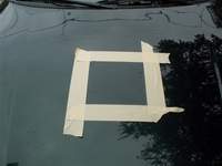
Now we are ready to make a template which will be
used to mark the are
we need to cut out of the hood.
Click on this picture to get a pre-made
template,
printing info labeled in this picture…
Temporarily assemble the two underside fasteners and plate with the
studs to the underside of the scope with the phillips screws. A little
soap on the screws will make them go into the unthreaded fiberglass easier
if they are really tight. (Make sure you get the screws in perfectly
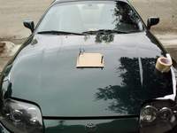
as there are no second takes here if you make a mistake). I had my scoop painted prior to starting this project. In order
to protect it from getting scratched I used an old motherboard box with
padding on the bottom.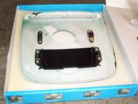
Now lay the cardboard template on top of the hood matching
up the
four holes to the four holes you have drilled.
Mark the outline of
the template on top of the hood with a thin marker or pencil.
I used some spare zip ties and a screwdriver to align the form with the
drilled holes.
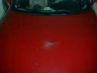
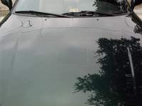
Once the outline is done you should end up with a nicely scratched hood
like in this picture.
Time to do some cutting. Mask off the are around the area you have marked.
This will help
prevent any scratching of the hood paint while working.
I also kept washing the hood with water to prevent scratching.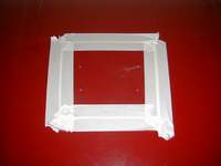
Once done cutting here is what you should see.
Using the sand paper, sand the edges of the hole so they are
smooth.
The hood is aluminum so it won’t rust. I didn’t bother
painting the edges
of the cut out. Clean the hood by spraying with a water hose.
Don’t do any wiping
or the metal particles from
cutting with scratch the paint. Remove
the tape.
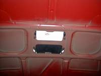
While the hood is drying lets cut a hole in the heat shield.
Here are some pics of the stock heatshield.
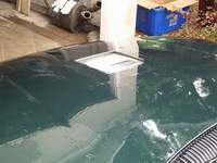
Now we put the whole thing back together.
Install the metal mesh into the scoop. Install the underside
studs and the plate with the studs to the underside of the scoop if they
aren’t already on. Then fit it on the hood.
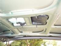
At this point I just put the nuts on to hold the
scoop in place while
I reinstalled the heat shiled.
Almost there. When installing the heat shield don’t
reinstall the center plastic fastners as they will need to also hold the
metal air guide.Before installing the hood scoop permanently decide if you want to use
the factory gasket or not on it. I used the factory gasket. Ron
didn’t. Instead of using the factory gasket and foam strips for the
underside of the scoop, I cut some thin strips of duct tape to serve as a
gasket. I don’t think the factory gasket will look good once
installed. It doesn’t wrap completely around the edge of the scoop
and it curves up and out so it will be seen when finished. Just make some
thin strips of tape and keep them slightly in from the edge. When
mounted, the scoop will lay very flush but the tape provides a little
cushion and seal that can’t be seen. I think the choice here depends
on the color of your car.
Insert the two factory fasteners in the middle of the air
guide. Holes are already there. Using a drill bit, punch small
holes through the four holes at the corners of the metal air guide through
the heat shield. Insert the plastic fasteners into all six holes of
the metal air guide. I had to slightly cut the new fasteners shorter
because there is little clearance between the frame of the hood and the
top of the hood.
One of the additional difficulties I had to work around was
a front
strut bar which required some cutting of the metal air guide.
You should
be able to see where the cuts needed to be made
to clear the strut bar. I
used metal cutters to do the job.
Since the metal air guide material is
soft its easy to cut.
Here is Kapi’s
car
Here is Ron’s car:
Notes: I sanded and painted the metal air guide before
installing.


![shifter[1].jpg (68310 bytes)](shifter%5B1%5D.jpg)
Stillway shifter installation instructions
Stillway
Shifter Installation Instructions
By:
Chris RomanoDisclaimer:
Follow these instructions are your own risk. The author will not be
held responsible in any way shape or form for any damage, buy which may occur.
By following these instructions, the reader releases all responsibility,
reliability, or blame in any way shape or form.
– This document was
created in hopes of making installation of the Stillway shifter easier.– Please reference the
Stillway Shifter installation document (written in Japanese) when following
these instructions.
Page
1.– When you open the
instruction booklet, page 1 details all of the parts necessary for
installation. Verify all components and proceed to page 2.
Page
2.Diagram 1. This
details the shifter and begins preparation for removal of the shifter. Begin
by unscrewing the factory shifter.Diagram 2. This
illustrates the cover that must be removed in order to loosen the bolt that
allows the shifter to be disconnected.
This cover covers the bolt required to release the shifter from the
transmission.Note: When
jacking up the car, please take ever precaution to avoid injury. You will
need to have the car in neutral so, please double check the emergency brake.
Also, a flashlight is recommended to view the necessary components.Diagram 3. The
bolt to be removed faces the rear of the car.
There are two bolts, be sure to only disconnect the bolt, which is on
the right in the picture. You
will need a 9/16th socket to remove this bolt.Diagram 4. Remove
the leather cover from the shifter. Remove
the ashtray, open the leather cover, which attaches to the shifter and
remove the plastic piece.
Page
3.Diagram 5. With
a 10mm socket, unbolt the metallic metal cover form the bottom of the
shifter. This piece helps in
keeping moisture and noise from entering the driver’s area.Diagram 6. Now,
carefully remove the metal cover then, the rubber boot.Diagram 7. More
detail on removing the rubber boot.Diagram 8. Using
the 10mm socket, remove the metallic plate.
Note the position of the plate before removing it!
This will give you an idea of how the sequential shifter works.
Page
4.Diagram 1. Remove
the metal pin that holds the factory plastic ring on the shifter.
Basically, this piece should push out.
Be very careful not to damage any of the plastic pieces inside the
plastic ring. Personally, I cut
mine off making it easier. You
will not need this piece later on.Note:
by cutting the plastic piece, you must use the sequential shifter, Toyota
does not sell this separately, and you will need to purchase a new shifter
if you decide not to use the sequential shifter.Diagram 2. Upon
removal of the plastic ring, be sure to replace the plastic inside guide
exactly how it was inserted. Be
careful not to damage this plastic piece!Diagram 1. Take
the metallic piece and place it on the shifter.
Carefully note the position of the hole be, sure to position this
exactly how it is pictured in the diagram.Diagram 2. After
the metallic piece is placed on the shifter, use the metal wedge provided to
secure the piece. Make sure
that the wedge is perfectly centered and not sticking out on either side.
Page
5.Diagram 1. Place
the shifter back into the proper position.
Be sure not to place the shifter on backwards!***Diagram 2. Ok,
now for the important part! There
are two guides; the left guide has an angle built in.
The right guide has a square shape.
The guide with the angle should be positioned on the left such that
the angle directs the shifter towards the 3rd gear gate.
Carefully study the #2 diagram on page 5. When the shifter is in the
center position, each guide should slightly touch the square piece on the
shifter. Now, these pieces should prevent the shifter from moving left and
right and guide the shifter into 3rd then back to 4th.
Basically, in this position, you should only be able to move the
shifter into 3rd and 4th gear. Make sure the shifter
cannot be moved left and right, do not allow play yet, allow the shifter to
be moved from 3rd to fourth smoothly. Tighten the angled guide
securely and be careful not to strip the bolts!
Then, place a washer on the left bottom bolt. There are two bolts,
one towards the front of the car and one towards the rear, place the washer
on the bolt that connects to the rear bolt.
The reason I did this was to allow easier shifting into 6th
gear. In order to go into reverse, the shifter will be moved to the far
right and then back. So, when
you drive the car, be sure to be very careful not to over shift into
reverse.Diagram 3. This
describes how the shifter should easily move from 3rd to 4th
gear and not from left to right. Notice
how once the shifter is between the gates, it will guide you into 3rd
then, into 4th gear…very nice ehe?!Diagram 4. Take
the metal ring and place it on the shifter as shown in the diagram.
Then, place the C clamp so that the ring will be secured.
Page
6.Diagram 5.
First, secure the shifter onto the transmission carefully!
Reconnect the bolt that connects the shifter to the fork. Then, place
the rubber cover back over the bolt. The kit comes with 4 rings and
instructions. On my car, I did not use these rings.
My car is a 1997 so; these may not be required on other year Supras.Screw
the new shifter on gently and position the hole on the shifter so that the
small allen bolt will screw in the “L” guide on the metal ring.Adjust
the shifter so that when the ring is turned into “normal driving mode”
every gear can be reached. There
are two modes, the first is normal mode, basically lift up on the ring and
turn so that the allen bolt locks and holds the ring in an up position
allowing all shifts to occur normally.
Once the shifter is at the proper height, use the bolt provided to
secure the height. On mine, the
allen bolt faces towards the back of the car…use this as a guide to
getting it adjusted properly. Of
course, every car will be different.Now,
to engage sequential mode, put the car in first gear and turn the ring so
that the ring drops. What will
happen is, 1st gear will shift into 2nd as normal.
Then, as you shift into 3rd, the guide will set the
shifter into 3rd gear…hence reducing the number of missed
gears! Then, the guide will
guide you into 4th gear. Notice in this mode that you shifter
cannot be moved from left to right. To get it back into normal mode, lift up
on the ring and turn to lock into normal position.Once
all steps are complete, take the car for a spin and make sure all gears are
smooth. Some adjustment may be
necessary. Note that the shifts
will feel a bit shorter and will take a little getting used to.
From neutral into first, you may need to angle the shifter towards 1st.
This is normal, the gates are designed to guide all shifts more
efficiently. However, no grinding should occur!
If your car grinds, adjust the unit so that the height is correct.
Once you have finished testing the unit, replace the rubber boot and
the metal cover that secures the boot.
Then, place the plastic cover and secure the leather to the shifter
allowing the ring to move properly. Replace
the ashtray and you’re done!Now,
practice with the unit in a parking lot.
BE SURE TO TEST NEAR YOUR HOUSE!
IN CASE THE SHIFTER NEEDS TO BE ADJUSTED!I
hope this helps! Enjoy the unit and I’ll see you at the races!Thanks,
Chris
Romano
http://www.angelfire.com/ab/teamdevious

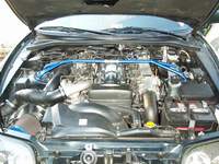
Stock fan mod
Stock Fan Mod
How to Control
your Electrical Fans with a Switch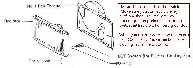
Or you can have the electrical
fans running all the time
by unplugging the fan harness hooked to the bottom of the radiator.

![]()
Egr mod’s
How to Defeat
the Engine Check Light after Performing ANY EGR ModWe apologize for the missing images, this article was missing for some time and brought back thanks to Archive.Org, unfortunately, some images could not be recovered
- Purpose: To
prevent check engine light from turning on after performing any egr mod.- Parts Required:
10K Ohm 1/2 watt resistor, Available
at Radio Shack (Part #271-1126), Electrical tape.- Time Required:
3 minutes.
Steps
::
Unplug the EGR gas temperature probe electrical
connector pictured below. Insert a 10K ohm 1/2 watt resistor into the connector (fig. 3).
This prevents a CPU trouble code from being tripped. Tape the connector with electrical
tape to prevent the resistor from falling out.Note:
it is hard to see the electrical connector on 97-98 models because it’s located
in the opposite position of 93-96, its between the manifold and engine valve cover towards the back
(firewall) – look for it using a flashlight. A screwdriver will help you unplug the
harness.


R
Removing the
TRAC
Butterfly
Stock Throttle Body With Trac
Butterfly

Modified Throttle Body with No Trac
Butterfly

HKS makes a kit to Remove
the Trac Butterfly (1312-RT001 / MSRP $95)


Here are the parts that need to
be removed while using the HKS kit.


Here is a cheaper way to block
the holes after you remove the trac plate, abortion use heavy duty epoxy to fill the
holes.
This is Inside the Trac system (trac motor
side),
All removed and filled with heavy Duty Epoxy


This is another way to remove the
traction butterfly, cut it off and weld it!
Clean looking huh?


![]()