
Author Archives: admin
Supra Problem Solvers
This page features technical articles and “how to” articles on repairs and modifications of the MKIV Supra.
There is a section on this page called “problem solvers” which will help with issues you may have with your Supra.
93-98 Supra TT FAQ

This page features frequently asked questions that you may have about your TT Supra. There are FAQs on specific topics like mods and maintenance as well as general FAQs about the Supra.
UH. WOW. Awesome Supra Video!
Thanks to MKIV reader: Alvaro for pointing us to this video.
Enjoy!
(disclaimer – a little bit of bad language – so don’t play this around your kids or at work)
Supra Videos Page 2
Here are more Supra Videos from around the Internet:
MKIV EURO LIGHTS ELECTRONIC BEAM ADJUSTMENT
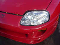
Purpose
– This mod will adjust your European Headlights Beam Height on the
Vertical Position.
Pros –
All 6 lights adjust up or down according to driver preference, used
in Europe extensively when increased weight is carried in the trunk of the
vehicle. In this case driver has the ability to adjust his beams
accordingly,
in order not to blind the coming vehicles. My purpose of using it, is
because I drive a lot at night, when traffic is limited to none, I can
adjust my lights a little bit higher than normal, so I can have a more
pleasant and less tiring trip (more light on the road).
Cons – I cannot think of something,
except abuse and either way, you (the
driver) can lower your beams in case you forgot them in an upper position,
since the coming drivers are going to notify you immediately (by flashing
the high beams).
Adjustment Capability
– The beams can move about 8 inches in height, when vehicle is facing a wall
at the distance of 6 feet. Significant adjustment
if one takes into consideration that on 100 feet distance the difference
can light up the trees if needed.
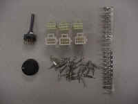
Needed tools and hardware
–
-
3 male connectors (6 – 10 pins)
-
18 male pins (make them 30, is
good to have some extras) -
3 female connectors (6 – 10 pins)
-
18 female pins (make them 30, is
good to have some extras) -
1 rotary switch (at least 4
position) -
Wires of the following colors:
RED, BLACK, WHITE, YELLOW, BLUE, GREEN. -
Length of each wire should be 14
feet and gauge 16-18. -
Harness protective sleeve 14 feet.
-
A decent looking knob, so it
doesn’t disturb the vehicle instrument panel harmony. -

– We are
fabricating the following schematic
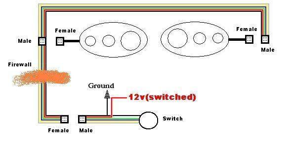
–
Install Photos


For power, we can use power from the
lighter, clock or any switched +12v. The circuit doesn’t have current while
resting on a certain position,
only when you change levels. The ideal is to
get power from the headlight switch relay, so your switch works only when
your headlights are on.
Serpentine Belt Drive Tension Damper System (Optional)
Serpentine Belt
Drive
Tension Damper System
(Optional)
– The 6-spd Supra TT use a
tension damper on the drive beltsystem, with each hard shift, the drive belt
tensioner spring vibrate, it get to the point were it will be bouncing back and
forth from the spring reaction under heavy load shifting, this tends to make the drive belt slip off the
accessories pulley’s, adding this tension damper system will damp the movement of the drive belt
tensioner.
Click Here for more information about the 6-spd
serpentine belt drive system & its related parts, from the 1993 NCF Book.
Click Here for more information about the Auto
serpentine belt drive system & its related parts from the 1993 NCF Book.
Here are the Parts numbers you
will need to get
Two 91511-G0845
Two 90179-08153
Two 90979-08171
Three 90116-08348
One 90901-16001
One 16622-46010
One 16621-46010
One 16602-46010
One 16620-46070
This what you will get,
top and lower brackets with hardware, tensioner & absorber.
Close up,
This is how it all looks put together,
Auto tensioner on the left, 6spd
tensioner on the right,
Here is everything installed,


Installation of the 6spd Differential, Drive Shaft & Left Axle
|
Here are the Parts numbers you |
|
1)
Here are diagrams and pictures of the parts you need to install, you will need
the differential, drive shaft and left axle.
– This is the 6spd differential,
when you order it from Toyota it will come assembled and ready to install, just
add oil (75w-90). if you buy it used then check its condition by removing the back
cover, or follow the manual instructions for testing.
– Here are some pictures comparing the 6spd rear with the auto
rear, notice the 6spd is longer front to back, also its left side is a littlie longer.
– This is the complete driveshaft, comes as two parts, front and
rear driveshaft, you will need both. if you buy it new, it will have to bought
together, Toyota does not sell them separately.
– Here is the Front driveshaft, the one on the left (short) is
for the Auto transmission, the one on the right (long) is for the 6spd
transmission, this is
due to the 6spd transmission being ~50mm shorter then the auto transmission.
– Here is the Rear driveshaft, the top one (longer) is for the
Auto tranny, the lower one (shorter) is for the 6spd tranny, this is due to the
6spd differential being longer then the auto differential (front to back).
– This is the Left axle, you will only need the left
6spd axle, due
to the 6spd differential being a littlie longer on the left side, the axle had to be
shortened littlie by Toyota, that’s why we only need the left axle in this
swap. Here is a table showing axle measurements from the 1995 Toyota repair
manual ,
TWIN TURBO, 6SPD TWIN TURBO, AUTO & ALL NA’s RIGHT AXLE 598.50
mm598.50
mmLEFT AXLE 547.50
mm553.50
mm


2) Here are
scans from the Toyota repair manual, scans for the replacing the differential,
drive shaft & axle.
– Differential,
– Drive Shaft
– Axle,


3) Here are
some pics of my own install,


Installation of the 6spd Sub-Tunnel
– Before we install the 6spd transmission
we will need to replace the auto sub-tunnel with the 6spd sub-tunnel, the 6spd
transmission sits few inches higher, the 6spd sub-tunnel will clear the tranny.
– Here is a Diagram from the toyota body
repair manual showing the differences in both sub tunnels. Notice how the auto
sub tunnel is flat, and how the 6spd sub tunnel rises few inches.


– You will need the following parts from
Toyota, shown
in this diagram in a circle,


– You will also need the top square marked part shown
in this diagram,


– Start by removing the driver seat,
e-brake, center console parts, radio and the auto shifter, you want to clear as
many parts as possible.
– Remove the ABS sensor from above the
auto sub-tunnel and modify it as shown in these pictures so it can fit the 6spd
sub-tunnel.


– Next remove the bracket holding the
e-brake, this will clear the area for the new 6spd sub-tunnel it fit in easier,
if you remove the carpet you will notice the spot welds, you basically need to
get a drill bit that is bigger then the spot welds, find all the spots and drill
them.

– Now almost all the welds are gone, but
the parts is still holding in, get under the car and start removing the rubber
holding the bracket in, Also you will need to work the top of the bracket to
brake it off or cut it with a Dremel,


– This is how it should look when your
done…


– Now you will cut the sub-tunnel, you
will need a jigsaw, notice from the top of the auto sub-tunnel how the outline
is easily shown, it extends all the way to under the radio, so make sure to
clear all the wires before cutting, you will need to use your drill to make a starting point
for your jigsaw, I started from the top tell I get close to the dash, then I
finished the rest from under the car.


– This how it should look after your done
with the cutting,


– You need to modify the 6spd sub-tunnel,
why? The 6spd sub-tunnel is a unversal part that fit left and right hand drive
supras, basically it have two threads on each side for the e-brake, cut the side
you don’t need (that’s the passenger side that need to be cut), this part will
fit better and easier with this modification,

– This is how it should look after its
been cut


– Here are the parts I cut off,

– Now test fit the new 6spd sub-tunnel,
insert it from under the car and upwards, make sure it have a good fit, do any
modification to achieve that, you want it to fit in snugly, Also you want the 2
e-brake threads to align with the e-brake, I had to use my Dremel to widen the
holes to get the screws to reach the sub-tunnel threads.

– After you test for the sub-tunnel
fitment and test the e-brake fitment, leave the e-brake screws holding on, we
will add more screw to hold in the new sub-tunnel, I added a screw to the front
of the tunnel as shown in these pictures,


– And another screw in the back, There is
a centering hole built in the new sub-tunnel and the body of the car, try to
line them up, lining this screw and the e-brake tells you you have a good
fitment, see these pictures,


– And another screw on the passenger side,
add as many screw tell you get he sub-tunnel it fit in nicely,

– There is a bracket that bolts between
the dash and the sub-tunnel, while your adding screws to the new sub-tunnel and
checking fitment, try to get this bracket to also align up, in my case I had to add
nuts under the bracket to make it high enough to reach the dash, see this
pictures,

– Once your happy with the fitment of the
new sub-tunnel, remove all the parts, visit your home improvement store and
buy ‘Liquid Nails, Heavy Duty’ Adhesive, we will use this to seal & glue the new
sub-panel to the body, this will reduce noise, keeps the dirt out and give some
strength to the two parts that have to come together, it takes up to a week for
this stuff to become totally hard, so don’t worry about it, just give it time,
it works well!

– Cover the 6spd sub-tunnel with the
Liquid Nails Heavy Duty, be generous with it, you will for sure finish one
bottle of this stuff, now insert the sub-tunnel from under the car and screw it
with the e-brake screws and the other new screw points, see these pictures,


– I used some of the Liquid Nails Heavy
Duty to seal all the gaps from the bottom as shown here,


– Your Almost Done! this how it should
look as soon as you put in the 6spd tranny,


