Category Archives: Parts Photos

Stock turbos

Turbo
#2 ready to come off
9.JPG (119103 bytes) 6.JPG (112277 bytes)
Manifold
31.JPG (77452 bytes) 32.JPG (73466 bytes)
Turbo
#2 Manifold

Block coolant drain plug

33.JPG (72591 bytes) 34.JPG (77685 bytes)

Turbo #2

35.JPG (69060 bytes) 36.JPG (59862 bytes)
37.JPG (69805 bytes) 38.JPG (62718 bytes)
7.JPG (83156 bytes) 8.JPG (98722 bytes)
EGCV
39.JPG (68792 bytes) 40.JPG (71224 bytes)

Exhaust Bypass Pipe

44.JPG (62948 bytes)
Both
Turbos bolted on
41.JPG (75615 bytes) 42.JPG (71789 bytes)
43.JPG (73313 bytes) 45.JPG (67816 bytes)
47.JPG (72890 bytes) 46.JPG (67905 bytes)
13.JPG (98616 bytes) 10.JPG (95225 bytes)
Turbos side by side
tt1.JPG (178233 bytes) tt2.JPG (162855 bytes)
tt3.JPG (169368 bytes) tt4.JPG (168400 bytes)
IACV
29.JPG (110056 bytes) 30.JPG (111532 bytes)
28.JPG (105419 bytes) 27.JPG (99391 bytes)
25.JPG (97892 bytes) 26.JPG (98789 bytes)
24.JPG (93137 bytes) 21.JPG (93952 bytes)
22.JPG (92701 bytes) 23.JPG (94372 bytes)
p3060012.jpg (198068 bytes) side.jpg (46180 bytes)
Turbo #1 – DAMAGED
14.JPG (96136 bytes) 18.JPG (97889 bytes)
17.JPG (99360 bytes) 16.JPG (87254 bytes)
20.JPG (101024 bytes) 19.JPG (99611 bytes)
c1016.JPG (185312 bytes) 15.JPG (97528 bytes)
c1017.JPG (184175 bytes) c1018.JPG (175821 bytes)
c1022.JPG (180839 bytes) c1019.JPG (176573 bytes)
c1021.JPG (172960 bytes) c1023.JPG (163732 bytes)
Turbo
Shield & Air Scoop
5.JPG (83723 bytes) 1.JPG (85405 bytes)
4.JPG (83572 bytes) 2.JPG (82702 bytes)


TT_stockers.jpg (15830 bytes)
Stock_turbos_removed.jpg (16939 bytes)

stocktwins.jpg (67274 bytes)

supra_su.gif (5342 bytes)

Stock plug, injector, fuel filter & fuel pump

A Clogged Fuel
Filter @80K miles of use

c1011.jpg (184991 bytes)

Fuel Pump Assembly

c1012.jpg (180293 bytes)  
c1013.jpg (187340 bytes)

c1014.jpg (177517 bytes)  
c1015.jpg (183632 bytes)

Stock Fuel
Injectors

c1024.jpg (166906 bytes)  
c1025.jpg (167570 bytes)

c1026.jpg (169667 bytes)

Spark Plugs
After Bad D
etonation

1.JPG (155392 bytes)  
4.JPG (153680 bytes)


Intake air controller (iac)

Intake Air Controller
(IAC)

dsc000

16.jpg (169689 bytes)

dsc00094.jpg (141760 bytes)  
dsc00095.jpg (129852 bytes)

iac.jpg (86603 bytes)


Intake manifold mini filter opened

Intake
Manifold Mini Filter Opened

dsc01387.jpg (169997 bytes)  
dsc01388.jpg (169435 bytes)

dsc01389.jpg (174491 bytes)  
dsc01393.jpg (179147 bytes)


Motec wideband air/fuel meter

Motec
Wideband Air/Fuel Meter

Click HERE
for the Manual

http://www.motec.com

view Arial, Helvetica”>

Professional Lambda
Meter

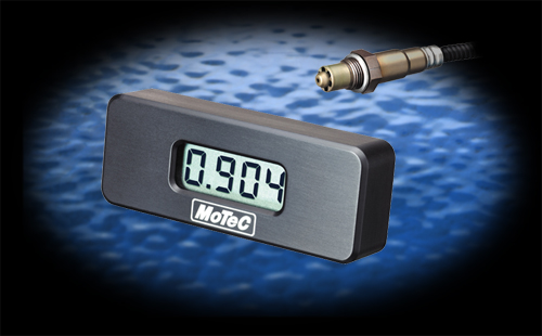
The MoTeC Professional
Lambda Meter (PLM) accurately determines exhaust gas mixture strength over
a wide range of engine operating conditions with a fast response time.
This device has been designed to be quick and easy to use, whilst allowing
a calibration engineer all of the power and configurability required for
OE emissions development and certification work.

Weighing only 135 gms and with a robust aluminium enclosure it can be
conveniently mounted singularly, on in multiples, in almost any
application. The operating range of the device is between 0.7 and 32.0
Lambda. For Gasoline/Petrol this equates to an Air/Fuel Ratio range of
10.3:1 to 470:1.

The display may be set to show Lambda, Air Fuel Ratio or Equivalence Ratio
for any sensor compatible fuel (Gasoline/Petrol, Alcohol, Gas, Diesel or
“blend” fuel as defined by the user). The resolution of the
display (decimal points), display update rate, display filtering,
backlight intensity may all be defined by the user with the Windows setup
software provided.

The MoTeC PLM provides an differential Analog Voltage Output that may be
connected to an Analog Meter or other measurement instrument such as a
Data Logger or Chart Recorder. The output may be defined by the user to be
linear or non-linear in relation to the measured units. The PLM also
supports 1mbit CAN and RS232 data links to devices such as the MoTeC
Dash/Logger for transmission of sensor and diagnostic data. Comprehensive
diagnostic and status channels are provided for.

The MoTeC PLM configuration determines exactly how it operates. The
initial configuration will allow the MoTeC PLM to be connected to a power
supply and sensor, displaying Lambda values without any modification to
the configuration. Changes can be made to the configuration to alter
various aspects of the MoTeC PLM. This includes the display parameter (eg.
to A/F ratio), display formats, analogue output scaling, sensor type,
sensor calibration, backlight intensity, etc. Standard configuration
templates for most common preferences are included. The user can manually
select the sensor used as Bosch LSU or NTK UEGO. Selecting
“Auto” allows the MoTeC PLM to determine the type of sensor
being used. The sensor can be user calibrated to compensate for sensing
aging and contamination.

The two prime applications for this device are for the development and
tuning of emission controlled vehicles and for use in motorsport. The
highly competitive motorsport environment requires that all aspects of the
vehicle are optimally calibrated and perhaps no area is more critical than
the engine.

The engine will normally give best performance at only one mixture
strength and the MoTeC PLM lets you accurately determine the direction and
magnitude of adjustments that need to be made to achieve this. The MoTeC
PLM can be used equally effectively on fuel injected and carburetted
vehicles. The versatility and practicality of the MoTeC PLM makes it
perfect for a wide range of applications, from garages to motorsport and
OEM calibration professionals.


dsc02197.jpg (91431 bytes)
dsc02198.jpg (108251 bytes)

dsc02199.jpg (99620 bytes)
dsc02200.jpg (92437 bytes)

dsc02201.jpg (80494 bytes)
dsc02203.jpg (139302 bytes)

dsc02208.jpg (135783 bytes)

dsc02204.jpg (153004 bytes)
dsc02205.jpg (111133 bytes)

 dsc02209.jpg (167740 bytes)


dsc01306.jpg (132610 bytes)
dsc01311.jpg (124607 bytes)

dsc01303.jpg (124920 bytes)

dsc01307.jpg (144677 bytes)
dsc01308.jpg (158573 bytes)

dsc01309.jpg (148111 bytes)
dsc01310.jpg (118942 bytes)


Stock clutch & new timing belt parts

Stock
Clutch Parts 80k miles

com.jpg (98401 bytes)

Clutch
Disk

c2.jpg (104930 bytes) c1.jpg (101629 bytes)
c4.jpg (104586 bytes) c3.jpg (101757 bytes)

Flywheel

f4.jpg (105674 bytes) f1.jpg (100118 bytes)
f5.jpg (78599 bytes) f2.jpg (110533 bytes)

Pressure
Plate

p5.jpg (105952 bytes) p1.jpg (106388 bytes)
p3.jpg (100200 bytes) p4.jpg (111614 bytes)

Under Cover/ Skid Pad

sp2.jpg (95606 bytes) sp.jpg (97951 bytes)

Timing
Belt New Parts

t2.jpg (99491 bytes) t1.jpg (105695 bytes)
t4.jpg (103449 bytes) t3.jpg (108169 bytes)

t5.jpg (99198 bytes)

Stock crank pulley

Stock
Under Drive Pulley(left) vs. Aftermarket Under Drive Pulley(right)

pulle000.jpg (24572 bytes)

pulle001.jpg (173729 bytes)

pulle003.jpg (16792 bytes)

pulle004.jpg (9670 bytes)    
pulle005.jpg (5910 bytes)


Stock twin turbo motor

Stock Twin
Turbo Motor
*for auto tranny

2jzgte.jpg (31351 bytes)

2jzgte1.jpg (35015 bytes)
2jzgte33.jpg (77799 bytes)

2jzgte11.jpg (83272 bytes)
engine_up.jpg (68794 bytes)

2jzgte2.jpg (37987 bytes)
2jzgte22.jpg (85150 bytes)

2jzgte3.jpg (40330 bytes)
2jzgte4.jpg (104659 bytes)


Stock intake manifold

Stock Intake
Manifold

ds

c00134.jpg (144967 bytes)

dsc00005.jpg (66512 bytes)
dsc00006.jpg (62338 bytes)

dsc00008.jpg (77051 bytes)
dsc00007.jpg (102847 bytes)

dsc00011.jpg (109851 bytes)
dsc00010.jpg (116569 bytes)

dsc00009.jpg (91233 bytes)
dsc00015.jpg (110154 bytes)

dsc00016.jpg (169689 bytes)

dsc00017.jpg (101900 bytes)
dsc00023.jpg (112603 bytes)

dsc00018.jpg (109418 bytes)

dsc00019.jpg (55064 bytes)
dsc00014.jpg (98830 bytes)

dsc00021.jpg (69200 bytes)
dsc00012.jpg (107788 bytes)


Stock mass air flow meter (maf)

Stock Mass Air
Flow Meter(MAF)

dsc00

100.jpg (114648 bytes)
dsc00101.jpg (119315 bytes)

dsc00096.jpg (97246 bytes)
dsc00097.jpg (105031 bytes)

dsc00099.jpg (106932 bytes)


SiteLock