
Category Archives: Other Info
how to replace spark plugs on supra twin turbo
How
to Replace Spark Plugs on Supra Twin Turbo
1)
Buy 6 New spark plugs, you have a choice of stock plug or any of your favorite
plug on the market,– Here is a list of the most commonly used spark
plugs,
- Stock Denso PK20R11, Comes pre-gaped at
0.043 inch (best on stock supra)- Stock NGK BKR6EP-11 (2978), Comes pre-gaped
at 0.043 inch (best on stock supra)- NGK BKR7E (6097), Comes pre-gaped at 0.032
inch (best on BPU & APU supra)- NGK BCPR7ES (3330), Comes pre-gaped at
0.032 inch (best on BPU & APU supra)– Also buy 2 crankcase
hoses, Toyota part number 12263-46010 & 12264-46010 (if needed),
if you have not replaced your hoses in a long time, chances are you going to
have a hardened crankcase hoses that will get damaged on removal, its always a
good idea to save new ones just in case you need them one day.
2) Remove the oil
cap and plug up the hole with a towel so you don’t drop anything down the oil
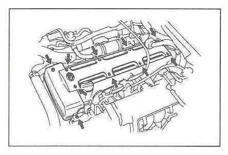
hole accidentally.3) With an Allen wrench(5mm) remove the top
cover of the engine, 10 screws. This best done on a cold motor.
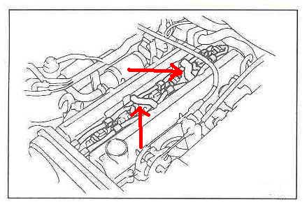
4) Remove the two crankcase vent
hoses that run between the valve covers. if they are hard to come off, clamp
them in the middle with pliers and twist the hose.
5) Using a small flat
head screwdriver, release
the wiring harness clips.6) Disconnect wiring
from the coil packs. two connectors per coil packs.7) Unbolt the coil packs holders. there
is a 10mm bolt on each side of the coil packs holders. there are 3 coil packs
holders.
8) Lift out the coil packs holders. Rock them back and forth if they are hard to come out, that will
help them come loose.
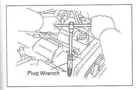
9) Use a deep well 5/8th spark plug socket to
remove plugs.
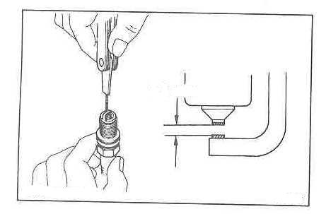
10) Gap (if needed)
& install the
new plugs (torque it to ~13 ft/lbs). or as shown on the manufacture interactions.
11) Install the coil packs. Make sure they are
seated.12) Connect wiring and re-clip wiring harness to clip. make sure each harness routes *below* the crankcase
vent.13) install crankcase hoses that you
bought (or previous ones if they are not cracked).14)
re-install cover and cover screws.15)
Remove towel from oil hole and replace it with the oil cap.
– Damaged your Coil Harness? Click Here
– All You Ever Wanted to Know About
NGK Plugs!


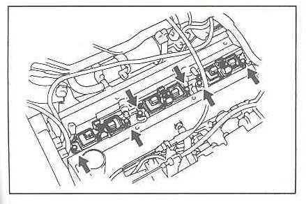
Valve stem seal replacement on ’93-’98 toyota supra turbo
|
Valve Stem Seal Replacement on ’93-’98 Toyota Supra Turbo |
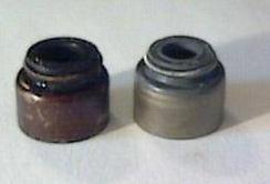 Old & New Seals |
|||||||||||||||||
|
Disclaimer: Attempt this job only at your own risk. Potential risks of this job include (but are not limited to):
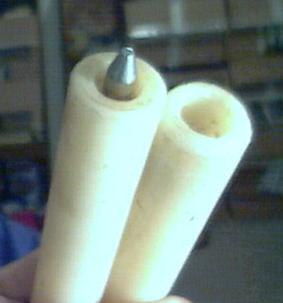
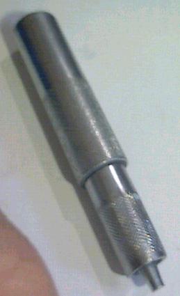
Tools Required:
Other Stuff:
Step 7:
Step 8:
Finish:
|
||||||||||||||||||


![]()
Fuel Pump Upgrade Guide
Fuel Pump Upgrade Guide
By
Jeff Lucius
(used with
permission of Jeff Lucius)
(This page has been modified,
Jeff Lucius
original page can be found
Here)
Editor’s Note: This
article was written by Jeff Lucius, a Dodge Stealth owner and is directed to
the Stealth/3000GT community. All references to “stock” sizes for pumps &
injectors are for the Stealth engine, however the information and test data
provided in the article will be of interest to the Supra community.
|
|
||||||||||||
Introduction
The solution for more power out of the
turbo models, in its simplest form, is just to add more air (increase boost) and
add more fuel. After a point, in order to add more fuel, a
larger-capacity-than-stock fuel pump is required, along with larger injectors
and a fuel-mixture controller. The fuel pump must be able to supply the amount
of fuel required by all the injectors in wide open throttle (WOT) conditions at
the maximum boost level anticipated. A 20% safety margin (that is, the pump can
supply 20% more fuel than is actually required) is often cited to avoid
overheating the pump or a momentary lean mixture (and possible damage to
pistons, valves, or rings).
In tank stock fuel pump is a constant or
fixed-displacement electric pump that is submerged in the fuel tank. It is
called a “wet type” pump because all of its components, including the internal
DC motor and impeller-type pump, are in contact with the fuel. The very-high
electrical resistance of gasoline (more than 1 megohm) prevents electrical
shorts inside the pump. A fixed volume of fuel is delivered for every revolution
of the pump. The amount of fuel discharged into the fuel line is determined by
how fast the pump rotates. The pump will rotate faster if the supplied voltage
is increased or if the fuel line pressure at the discharge port is reduced. If
the pressure at the discharge point exceeds a certain pressure point, a relief valve built
into the pump opens to reduce pressure inside the pump. There
is also a spring-loaded check valve in the pump to preserve high pressure in the
fuel line when the pump is stopped.Fuel pumps supply fuel volume; they
do not create pressure in the fuel lines. In a return-line system, the fuel pressure regulator restricts the return fuel flow
in order to create pressure in the supply line. As the fuel supply line pressure
increases, such as during boost conditions for forced-induction engines, the
pump has to work harder (it actually rotates slower and the current draw
increases) and so the volume flow decreases. Pumps also have a ceiling capacity
where flow drops off rapidly above a certain line pressure (though this might be
higher than the relief valve opening pressure).Flow rate is measured in
gallons per hour (gph), liters per hour (lph; 1 gallon = 3.7854 L), or pounds
per hour (lb/hr). The average density of gasoline is 690 to 760 g/L (or 5.76 to
6.34 lb/gal).
How to Select
– Know Your Needs
In order to determine
what size fuel pump you need, you must first decide on (or know) the injector
size and the maximum boost you plan to run. For example, many people
upgrade the stock 360 cc/min injectors to 550-cc/min injectors. Six 550
injectors theoretically will flow 198 lph at 100% injector duty cycle (IDC). A
boost pressure of 25 psi would probably be considered by many to be the upper
limit for most street engines. The fuel pump you need then must be able to
supply at least 200 lph at 68 psi fuel line pressure (43 psi base line pressure
for 3S turbo models plus 25 psi to compensate for boost pressure in the plenum)
at the voltage the pump is receiving. The voltage the pump receives is critical
because flow can vary by 5 to 80 percent per volt depending on the
particular pump, the voltage level, and the line pressure.
– Get the
Ratings
To determine if a fuel pump can meet your needs, you will
need either a flow chart (see the examples below) or a flow rating
for the pump. A flow chart is the best choice because it shows the measured flow
rate over a range of line pressures, usually in increments of either 5 or 10
psi, for a particular supplied voltage. A flow rating cites the flow rate at one
line pressure. For a flow rating to be useful it also must state the supplied
voltage. If the voltage is not stated, it is probably fair to assume it is 13.5
volts. The flow rating pressure is usually 0 psi (also called the free-flow
rating) or some integer multiple of bars. Three bars (43.5 psi) is a popular
rated pressure for electric pumps, as is 5 bars (72.5 psi).– Check
the Current
Pumps are usually tested and rated at 12 or 13.5 volts.
Unfortunately, substantially less than 12 volts may be reaching the pump. I have
measured current at the 10.2 to 10.5 volt range at the pump at 15 psi boost as
shown on my web page
2-fuelpumpvoltage.htm.
The cause of this is the relatively small gauge wire used in the pump circuit,
the inclusion of the engine control relay in the circuit, and the use of an
additional relay and resistor in the turbo models to reduce voltage to the
pump at idle and low-load cruising. Sometimes re-wiring the connector at the
resistor will restore voltage to the 11.5 to 12 volt range.Another method to increase voltage to the fuel pump is to use one of the
following “step up” voltage regulators, which would include re-wiring the fuel
pump circuit similar to the methods described above.
-
Kenne Bell
Boost-a-PumpTM
MSD
Fuel Pump Booster
Jacob
Electronics Accuvolt FR-750
Aeromotive
Billet
Fuel Pump Controller
Ramchargers
Volt Blaster
– If You Still Need More
If you need more fuel than one pump can supply, then I have been told that
two 50-mm Denso pumps (like the VR4 and Supra pumps) will fit in the tank. Because of the heavy current draw (above 16 amps
for each pump), you must install another circuit to supply power for the second
pump. Two Denso pumps on the same circuit will lower voltage far below 12 volts
and have unacceptably lower pump flow. The Walbro fuel pumps are narrower than
the Denso pumps listed here and two will easily fit side-by-side through the
tank opening and on the assembly. The Bosch and Nismo fuel pumps have a larger
diameter than the Denso pumps.The diameter of the fuel supply lines may
restrict the amount and pressure of fuel that can be delivered regardless of
pump capabilities. There is always some pressure loss in the lines, filter, and
rails. For those of you interested in increasing the supply line size as well as
the fuel pump capacity, remember that volume flow in smooth round pipes (with
turbulent flow like in fuel lines) is proportional to the 2.5th power
of the fuel-line radius. So a 33 percent increase in the fuel pipe diameter will
double the volume flow (1.3332.5 = 2.05). The stock high-pressure
supply line is an AN-5 pipe (5/16″ outside diameter). An AN-8 supply line is
sometimes recommended to support 550 bhp. Bear in mind though, that many
recommendations come from the non-turbo hot-rodders that use low fuel-line
pressures and low-pressure fuel pumps. The loss of few psi due to small fuel
lines affects low-pressure systems much more than it affects high-pressure
systems like ours. Our high-pressure pumps just need to work a little harder to
maintain correct line pressure at the injectors.– Pick a
Pump
There are basically four fuel pump manufacturers to consider
when upgrading the in-tank fuel pump: Bosch, Walbro, Nismo (Nissan Motors), and
Denso. If you are considering eliminating the in-tank pump in favor of an
external pump, there are other choices for manufacturers, as well as much
larger-capacity pumps available.
Weldon Racing Pumps is an example.This page focuses
on in-tank replacements. Only Denso makes a direct “drop-in” replacement for the
stock pump (a 50-mm diameter pump made by Denso). The Bosch, Walbro, and Nismo
pumps require modifications to the fuel pump assembly.
Bosch Fuel Pumps
Bosch makes excellent fuel pumps. Porsche uses them in
the 928 models. Bosch pumps don’t flow much at 43 psi line pressure, but at very
high line pressures they tend to flow better than other pumps. However, for our
cars they are still inadequate for injectors larger than 450 cc/min. Considering
that Bosch pump model 10208 is 2.45″ in diameter and 7.5″ long, and requires extensive modifications to
the pump assembly to make it work, there are better choices out there that cost
less, flow more, and drop right in. The only advantage the Bosch 10208 has over
the other selections here is that it flows 158 lph at 100 psi line pressure, far
better than any of the others. For more information about Bosch pumps see the
links below.
http://www.newwave.net/~flanham/wlanham/fuel/pumps.html
http://www.theoldone.com/components/fuelpumps/
http://www.alltrac.net/tuning/fuel.html).
The picture below
is adapted from http://www.theoldone.com/.
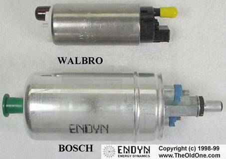
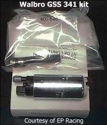
Walbro Fuel Pumps
There are basically three models of Walbro pumps. For each of these three models
there are three “sub-models” that differ only in the fuel line connection. The
Walbro GSS242, GSS250, and GSS278 are 190 lph models. The Walbro GSS307, GSS315,
and GSS317 are 255 lph models. The Walbro GSS340, GSS341, and GSS342 are 255 lph
high-pressure models. The Walbro 341 model (also called the 255 lph HP) would be
the best Walbro model.The Walbro pumps are
inexpensive, only about $100 to $150.
Both the 315 and 341 models will work if 450 cc/min injectors are used and about
12 volts are supplied to the pump. The 341 model would be minimally suitable for
use with 550 cc/min injectors in the VR4 if voltage to the pump is maintained at
13.5 volts or more. Walbro models 315 and 341 flow similar amounts of fuel up to
about 55 psi line pressure (12 psi boost). A change in the relief valve design
of the 341 permits better flow than the 315 at higher pressures. The reason for
this is that relief valves often allow some amount of fuel to pass below the
cracking pressure. The 341 model uses a relief valve that seeps less fuel at
pressures above 60 psi than the 315 model’s relief valve.Look at the
following links for Walbro fuel pump flow data:
http://www.roadraceengineering.com/fuelpumpflowrates.htm
http://www.autoperformanceengineering.com/html/fuelpump.html
http://www.vfaq.com/pump-Walbros.html
http://www.supras.nl/modsFuelPump.htm.
Nismo/Skyline Fuel Pumps
The Nissan Skyline fuel pump has held a
legendary position as the ultimate upgrade fuel pump for the VR4, reportedly
flowing 310 lph at 43 psi. Unfortunately, there are no hard data to support
this. Both Mines and HKS sell upgrade pumps for the
Skyline models that flow “only” 270 and 280 lph, respectively. Given HKS’s
propensity for exaggeration (see below), I would guess a 270 lph pump (at 43 psi
with 13.5 volts) is as large a “Skyline” pump as is available. A’PEXi sells an
upgrade pump for the Skyline. I have not seen a flow rating for this pump but I
would guess it is also 270 lph. The R32 Skyline came with a 190 lph pump, and
the R33 Skyline had a 195 lph pump. I am not sure about the current R34 model,
but if it is the same as the fuel pump in the Nissan 300ZX turbo (and I have
heard from several sources that it is), then it flows about 255 lph (at 43 psi
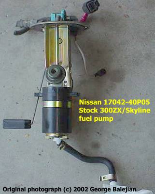
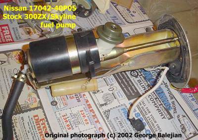
with 13.5 volts).George Balejian contributed
the pictures below of his installation of the Nissan 300ZX/Skyline pump. Some
modification to the fuel pump assembly is required. George had RC Engineering
flow test this pump. The results (see the table in the Summary) show this
pump flows like the Cosmo and Supra Turbo fuel pumps, depending on fuel line
pressure.
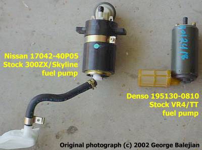
Denso Fuel Pumps
Denso fuel pumps that have a 50-mm diameter and have
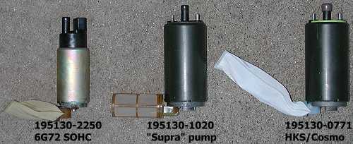
part numbers that start with 195130 are direct “drop-in” replacements.The chart below shows
the flow test results for the stock Mitsubishi 3000GT VR4, The Mazda Cosmo 20B
(special thanks to Paul B.
Prentis, Jr. for this data), and the Toyota Supra Turbo MKIV fuel pumps. All
pumps are used (about 56,000 miles on my original Stealth TT pump; about 2,000
miles on the Supra pump; I’m not sure how many miles on the Cosmo pump).
RC Engineering, Inc. (Torrance, CA;
310-320-2277) performed these tests using a pump dynamometer (this service costs
about $50 per pump). Testing can also be performed by
Kinsler Fuel Injection, Inc.
(Troy, MI; 248-362-1145).For the VR4 and Supra pumps, testing was
performed on March 28, 2001 with a pump supply voltage of 13.5 volts. The Cosmo
pump was tested on September 5, 2001 at 13.8 volts. The test fluid specific
gravity was 0.76 (or 6.34 lb/gal). The complete RC Engineering flow test data
are reproduced in an Excel spreadsheet:
fuelpumpcomparo.xls.
On the flow chart above I note the theoretical maximum-flow
capabilities of popular fuel injectors for the VR4. Please note that most
injector manufacturers recommend a maximum, continuous IDC of 80 percent, and
that peak injector output often occurs at only 90 to 95 percent IDC.The
VR4 alternator in good operating condition tries to maintain at least 13.4 volts
at ambient temperatures under 140ºF (60ºC). I see my alternator output drop to
13 volts at WOT using the TMO datalogger. I think it would be rare for VR4 fuel
pump to receive the full voltage output of the alternator. As I mentioned above,
10.5 volts or less at the pump can be typical (it is what I measured on my TT
before and after the relay/resistor bypass mod), with 11.5 to 12 volts sometimes
available at the pump after the resistor/relay by-pass modification. Because of
this, I also estimated pump output at 12 volts. This estimation may be a little
high as will be seen in the next chart.The chart above points out the
limits of the stock VR4 fuel pump (at least a used one with 56000 miles on it)
with the stock VR4 360 cc/min injectors. Above 20 psi boost (63 psi line
pressure) the pump operating at 13.5 V cannot supply enough fuel for the
injectors. At 12 volts the pump runs out of capacity below 15 psi. Boost
pressures of 12 to 15 psi are widely considered the safe limit (if detonation is
controlled) for a 3000GT VR4 or Stealth TT with a stock fuel system (regardless
of which turbo is used). I have instructions for measuring voltage at the fuel
pump on my web page 2-fuelpumpvoltage.htm.My old stock VR4 pump tested 10 lph less than what the stock pump is
rated at, which is 180 lph at 43 psi at 13.5 volts (but I have never seen
Mitsubishi or Denso documentation for this). This may be due to the fact that
electric fuel pumps run constantly. After 56000 miles and 8 years of service the
armature bushings, brushes, commutator, pump vanes, and the rollers or gears
have worn causing a loss of pressure and flow. Reduced flow from older pumps is
something you should consider when increasing boost or upgrading injectors.
As I have mentioned, voltage to the pump is critical in determining how
much fuel is discharged. John Cribb, a TT Supra owner, had his new Toyota Supra
MKIV fuel pump (Denso 195130-1020) flow tested at Kinsler Fuel Injection, Inc. at
five different voltages. Kinsler measured the flow and current draw (amperage)
at each of these voltages, from 40 to 100 psi line pressure. The test fluid
specific gravity was 0.79 (or 6.6 lb/gal). John was kind enough to share the
results with us. They are available in an Excel spreadsheet,
jcribb-supra-fp-test.xls.
I added the LPH column and made minor changes to the structure of the original
spreadsheet. The data have not been changed. Many thanks to John Cribb for
sharing this data.In the chart below, I plotted the volume flow versus
fuel line pressure for the five voltages the Supra pump was tested at. For
reference, I included the flow-test results for the stock VR4 pump at 13.5
volts. The flow rates for John’s Supra pump are bit lower than those for my
Supra pump. This may be attributed to one or more of the following factors: a
difference in testing methods (RCE vs. KFI), a difference in test fluid specific
gravity (less dense fluids may pump easier), and Denso production variations.Nevertheless, one of the most interesting features of this data is the
tremendous change in output at lower voltage levels. The change in output from 9
volts to 12 volts at 40, 50, and 60 psi line pressure is 70%, 200%, and 236%,
respectively. This would be about 23%, 67%, and 78%, respectively, per
volt change in output! Obviously, this fuel pump responds well to small
increases in voltage. Output increases are less dramatic at levels above 14
volts, but still significant. This type of variation with supplied voltage may
be typical for other high-flow Denso pumps. We won’t know until further testing
is performed.Because the Supra pump flow varies so much with supplied
voltage, the actual voltage at the pump determines the injectors sizes that are
appropriate to use with the pump. If six injectors are used and if the injectors
can actually flow at their rated output at 100% injector duty cycle (always
open), then the general recommendations below for injectors sizes are suggested
for different supplied voltages.
11V: up to 360 cc/min
12V:
up to 450 cc/min
13.5V: up to 550
cc/min
14V: up to 600 cc/min
16V:
up to 750 cc/min
18V: up to
880 cc/min
Mach V sells the
Buschur Racing Upgrade Pump that is a direct drop-in replacement with a claimed
capacity of 369 lb/hr at 70 psi line pressure, or about 231 liters (61 gallons)
per hour at 70 psi (there is no mention of supply voltage). This pump must be
the Supra Turbo pump.The Cosmo pump performs similar to the Walbro 341
pump and would be good for 550 cc/min injectors only if 13.5 volts or more are
supplied to the pump. Otherwise, it is safe to use with 450 cc/min injectors.
The Cosmo pump, or Denso 195130-0771, is sold by HKS with their part number
1407-001US. For many years this pump was advertised by retailers with a rating
of “340 lph, 165 psi” or “90 gph, 165 psi”. I am not sure what that means. The
Cosmo pump might flow 340 lph at 0 psi line pressure and 13.5 volts. But it only
flows about 260 lph at 43 psi and 13.5 volts. HKS now advertises this pump on
their web page http://www.hksusa.com/products/?id=717 with a rating of 71 gph
at 45 psi (no voltage listed) and a suggest retail price of $835 (wow!). This
might be about right for the Cosmo pump at 14 volts – 269 lph at 45 psi. From
the RCE pump tests, it looks like the relief valve for the Cosmo pump is set at
about 90 psi, so I’m not sure what the “165 psi” in the old advertisements
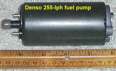
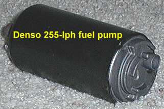
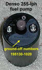
meant.The pictures below are of the pump that was sold to me as “same
as the HKS 90-gph pump”. The part numbers were ground off, but I installed it
anyway in the Spring of 2000. On March 13, 2001 I removed the fuel pump from my
tank and inspected the ground-off numbers with a 10-power hand lens. The
remnants of “1020” can still be seen. This pump is the Toyota Supra Turbo fuel
pump. I sent this pump and the old stock one to RC Engineering for flow testing
and the results are shown above. The Supra Turbo pump can be purchased for about
$200 (sometimes less) from places like Conicelli Parts Center. In retrospect, I never should have
accepted a part that had the part numbers ground off, and will not in the
future. On a humorous note, this pump actually performs better than the “HKS”
pump.
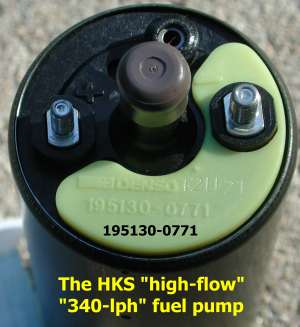
Below are some pictures of the HKS fuel pump that I purchased. I
returned it after seeing it was the Cosmo pump, which flows less than the Supra
pump I already had. I cannot caution people enough to avoid the “HKS” pump (if
it is actually Denso 195130-0771) when it is sold at the exorbitant price of
$400 to $800.
Summary
Please note that flow values in the tables below are for 13.5
volts supplied at the pump. Voltage at the pump in your car may be only 10.5 to
12 volts, and so actual flow may be much less than the values indicated below.
| Fuel Pumps for the 3000GT/Stealth |
||||
|---|---|---|---|---|
| Name | Part Number |
Rated flow lph @ 43psi @13.5V |
Rated flow gph @ 43psi @13.5V |
Comments |
| Mitsubishi VR4 | Denso 195130-0810 |
180 | 48 | This pump also may be used in the Celica GT-4. Good for use with 360 cc/min injectors up to 12-15 psi boost when voltage is less than 12 volts. Light blue or green tag on top. |
| Bosch | Bosch 10208 |
210 | 55 | Flow data is from The Old One Good for use with 450 cc/min injectors. 62.2 mm diameter; 7.5″ long. Requires modifications to the pump assembly. |
| Mazda RX-7 Turbo | Denso 195130-0782 |
235 | 62 | Road///Race Engineering says 210 lph @ 12 v. Good for use with 450 cc/min injectors. |
| Walbro | Walbro GSS 341 |
255 | 67 | This flow data is from Auto Performance Engineering. Good for use with 450 cc/min injectors. The Walbro 341 can be purchased from Extreme PSI for about $100. An adapter is required for the pickup tube and electrical connection. |
| Nissan 300ZX Turbo (Skyline the same?) |
Nissan 17042-40P05 |
255 | 67 | This flow data is from RC Engineering tests for George Balejian. Requires modification to pump assembly pickup tube. Good for use with 550 cc/min injectors if supplied voltage is kept high. Dealer list price is ~$300. ABC Nissan (1-800-500-8722) may sell it at a 25% discount (~$227). |
| Mazda Cosmo 20B | Denso 195130-0771 |
260 | 69 | This flow data is from RC Engineering tests for Paul Prentis Jr. Road///Race Engineering reports 250 lph flow. Good for use with 550 cc/min injectors. Yellow tag on top. |
| “HKS” High Flow | Denso 195130-0771 HKS 1407-001US |
260 | 69 | I bought one of these pumps and the Denso part number is 195130-0771, the “Cosmo” pump! I sent it back. HKS used to claim “340 lph”. Now they claim “71 gph @ 45 psi” (269 lph). The Cosmo pump would need over 14 v for that kind of output. HKS MSRP = $835!!!!!! |
| Mines Skyline | Mines ??? |
270 | 71 | Mines and their retailers do not mention voltage or pressure. |
| HKS Skyline | HKS 1407-RN018 |
280 | 74 | Actual flow may be closer to 270 lph. Voltage and pressure are not mentioned. More information at http://www.racecarnewmedia.com/hks/news200012b.htm |
| Toyota Supra Turbo | Denso 195130-1020 Toyota 23221-46110 |
290 | 77 | 260 lph @ 43 psi; 220 lph @ 58 psi; @ 12 V 1. 290 lph @ 43 psi; 266 lph @ 58 psi @ 13.5 V 2. 290 lph @ 43 psi; 260 lph @ 58 psi; @ 14 V 1. Good for use with 550 cc/min injectors. Buy this pump for about $200 at Conicelli Toyota. Black tag on top. |
|
1 Measured by Road///Race Engineering. 2 Measured by RC Engineering. |
||||
The table below uses data from the RC
Engineering tests of the Denso and Nissan 300ZX pumps and from what Walbro
advertises for their GSS341 pump. RCE tested my VR4/TT fuel pump (used for
56,000 miles) and my Supra MKIV pump (used for 2,000 miles). I thank Paul
Prentis, Jr. for sharing the RCE test results for his Cosmo pump and George
Balejian for sharing the RCE test results for his Nissan 300ZX pump. The
complete data are available in an Excel spreadsheet:
fuelpumpcomparo.xls.
| Fuel Pump Flow Tests Comparisons |
||||||
|---|---|---|---|---|---|---|
| Pump | VR4 used 195130-0810 |
Bosch 10208 |
Walbro GSS341 |
Mazda Cosmo 195130-0771 |
300ZX 17042-40P05 |
Supra MKIV 195130-1020 |
| Volts | 13.5 | 13.5? | 13.5 | 13.8 | 13.5 | 13.5 |
| PSIG | Tested Flow in liters per hour (lph) | |||||
| 40 | 176.66 | ~213 | 257.41 | 268.77 | 256.78 | 297.16 |
| 45 | 168.45 | – | – | 258.04 | 253.63 | 288.96 |
| 50 | 158.36 | 201.90 | 242.27 | 253.00 | 249.84 | 280.13 |
| 55 | 148.90 | – | – | 238.49 | 243.53 | 271.29 |
| 60 | 135.65 | ~195 | 223.34 | 229.65 | 241.01 | 263.09 |
| 65 | 126.18 | – | – | 217.04 | 236.59 | 247.32 |
| 70 | 102.21 | 189.2 | 208.20 | 204.42 | 231.55 | 231.55 |
| 75 | 0 | – | – | 181.70 | 213.88 | 208.83 |
| 80 | 0 | ~179 | 174.13 | 163.41 | 196.85 | 194.95 |
| 85 | 0 | – | – | 138.80 | 176.66 | 173.50 |
| 90 | 0 | ~168 | 143.85 | 117.35 | 143.22 | 161.51 |
| 95 | 0 | – | – | 0 | 127.45 | 134.39 |
| 100 | 0 | 157.7 | 71.92 | 0 | 0 | 0 |
Conclusions
Denso fuel pump 195130-1020 (the Supra Turbo MKIV
pump) is one of the best in-tank upgrade choices if you are using injectors up
to 550 cc/min and are providing at least 13.5 volts to the pump. When higher
voltage is supplied, the Supra pump is good for injectors up to 880 cc/min. At
13.5 supplied volts no other in-tank pump flows significantly more fuel up to 70
psi line pressure or 27 psi boost. It is a direct drop-in replacement; all other
non-Denso choices require some modification to the assembly. It is as quiet as
the stock pump. Best of all, it can cost only about $200. One disadvantage of
the Supra pump is its relatively heavy current draw and large decrease in flow
as supplied voltage lowers. Good, heavy-gauge wiring (meaning re-wiring the fuel
pump electrical circuit) is a requirement to get the most out of this pump.The Walbro 341 model (also called the 255 lph HP) flows about 10
to 40 lph less than the Supra Turbo pump up to about 70 psi, when 13.5 volts
are supplied to both pumps. However, at 12 supplied volts, the Walbro 341
outflows the Denso 195130-1020 above 50 psi line pressure (compare John Cribb’s
Supra pump data to the Walbro charts). The Walbro 341 is an excellent choice for
450 cc/min injectors, especially if the fuel pump has not been re-wired. It can
be used with 550 cc/min injectors if 13.5 volts are supplied. Some slight
modification to the pump assembly is required and it is not as quiet as the
Denso pumps. The price is even less than the Supra pump at $100 to $150.Whatever pump you decide to go with, the Cosmo and 300ZX/Skyline pumps
are also good choices, the voltage at the pump is critical for good flow. Check
the voltage at the pump. If it is below 11 volts try the resistor/relay by-pass
modification first to see if voltage increases to 11.5 to 12 volts. For more
current you will have to re-wire the circuit and maybe add a step-up voltage
regulator.If you have pump dynamometer measurements for any pump that
fits the 3S cars please let me know the results and I will share them on this
web page (send me
email).
Except for the small gif and jpg images, the content, images,
photographs, text, and multimedia displayed are Copyright © 2000-2003 by Jeff
Lucius and K2 Software. All rights reserved. No part, section, image, photo,
article, or whole of this site may be reposted or redisplayed without permission
of the author.
Page last updated March 11, 2003.
![]()
Tint removal
Tint Removal
by Aaron Rountree
Tools: Ammonia
or ammonia product (Windex), scrubbing pad, razor blade, black trash bag and
paper towels.

Step 1: To
remove old tint from side windows use your razor blade to peel up a corner
and then pull the tint off. For the rear window with defroster spray the window
with ammonia generously then stick the trash bag on it letting it sit in the
sun to soften the adhesive. You may be able to pull the tint right off to
begin with but be careful not to damage the defroster. DO NOT SCRAPE WITH
A RAZOR BLADE.

Step 2: To
remove the left over adhesive on the side windows scrape as much off as possible
with the razor to minimize the mess later on. Spray ammonia on the windows
generously to start softening up the adhesive.

Scrub the windows with
a soft pad, keep the window wet with ammonia. As you remove from sections wipe
off loose adhesive with paper towels.

The side windows should be much
less messy than the rear window if you’ve scraped as much adhesive off beforehand.

Finished: Keep
scrubbing and wiping excess off until you have a clean window.

![]()
Techtom obd1 reader
TECHTOM
MDM-100
MULTI DISPLAY MONITOR
For Toyota OBD1 Cars
DISPLAY STANDS FOR EXPLANATION INJ 00.00 ms Injector Duty Time Duty 0.0 % Injector Duty Percentage IGT 000 deg Ignition Timing Degree RPM 0000 rpm Engine Speed RPM SPD 000 kmh Speed Kmh SPD 000 mph Speed Mph WTMP 00 c Water Temp Celsius WTMP 00 f Water Temp Fahrenheit THP 0.0 deg Throttle Position Degree ISCS 000 STEP Idle Regulator Valve Steps ISCS 00.0 % Idle Regulator Valve
PercentagePIMt 0.0 kpa Intake Manifold Pressure
TurboPIMn 0.0 kpa Intake Manifold Pressure Non-turbo AFMv 0.00 v Air Flow Meter Signal Voltage AFMg 0.00 g/s Hot Wire Output g/s Karmen Output Time STA-up on/off Cold Start On / Off WARM-up
on/offWarm up On / Off A/F-L on/off A/F Adjustment Control On
/ OffA/F-R on/off A/F Adjustment Control On
/ OffKNOCK on/off Knock Sensor On / Off STA-sw on/off Starter Switch Position On
/ OffIDL-sw on/off Idle Switch Position On
/ OffA/C-sw on/off Air Conditioning On
/
OffNTL-sw on/off Neutral On > Off O2-R
lean/richO2 Sensor LEAN / RICH O2-L
lean/richO2 Sensor LEAN / RICH DIAG NG/OK Diagnostic Condition OK
/ NGMAJOR PARAMETERS Simply
access these major parameters with the simple 3-button control.
FEATURES
Easy connection – plugs into ROUND diagnostic port under
dash drivers side
16-bit CPU for high-performance processing
Heat resistant ABS plastic case
Industrial grade LCD screen with back lighting
Special heat resistant cable
Electronic control of LCD brightness and contrast
Nonvolatile memory – no need for backup battery
3-button control for ease of use
Normal Finish
Carbon Fiber Finish
1 Din Size


