|

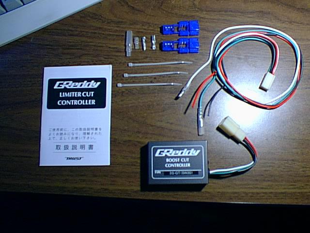
The control unit on the Supra TT has an internal boost cut
which can only be removed with special programming. The alternative to this special
programming is to use the Boost Cut Control from Greddy. This electronic device can
be installed in Supra control unit.
Tools/parts required:
Phillips screwdriver, 10mm socket, wire clippers, crimping tool.


(See addendum at bottom of post for JDM ECU: pin B will be 2 pins to the left.)
| Red |
Splice to wire marked ‘B’ on ECU diagram |
| Black |
Splice to wire marked ‘E’ on ECU diagram |
| Green |
To turbo pressure signal wire marked ‘P’ on ECU
diagram(BLACK/YELLOW STRIPED WIRE) |
| White |
Wire to the TPS, away from the ECU(BLACK/YELLOW
STRIPED WIRE) |


Precision
Adjustment of the BCC Output Voltage
Inside the BCC shell
is a screw that provides adjustment of the peak voltage output.
Since the ECU uses the TPS V data for many functions, you want this set
only as low as needed to avoid fuel cut, and not unnecessarily lower.
The setting as it comes from Greddy is usable but lower than necessary,
and varies from unit to unit. You could roughly set it by just repeatedly
driving your car at max boost and slowly turning the screw
counterclockwise to reduce the peak voltage output until you no longer hit
fuel cut. But this is a crude method compared to adjusting it
precisely by measurement with a volt meter, as follows:
1.
The Connections for Voltage Tune assume your BCC is uninstalled. To
Volt tune after the BCC is fully installed, you will need to disconnect
the BCC’s green and white wires to proceed, but may leave the red and
black wires installed.
2.
Red BCC wire to any 12V source such as car battery +
3.
Black BCC wire, and negative probe of your voltmeter, to ground of same
battery.
4. White
BCC wire to any automotive voltage source of 5-12V. Simplest
is to use the 12V source same as red wire. Others have used the 6V
output of a battery charger, doesn’t matter because any Input of 5-12v to
the BCC will give the same Output for a given adjustment screw setting.
5.
Green BCC wire to the positive probe of your voltmeter.
6.
Turn screw to provide voltmeter reading of Nearly but Not More
Than: 4.3 V for 93-95 cars; 4.1 V for 96-98 cars.
Addendum for JDM ECU:
Pin B should be 2 pins over as shown below.

Happy Boosting!

|


The text field of this page is too small to house the pictures with text on them, makes for a hard install of the greddy bcc/supra store bcc.
thanks
I’ll check this right away.
Aron