
getrag
The
Final Answer to the RedLine D-4 Question
Dear
Mr. Lance M. Wolrab, orderAttached
you find the answer to your questions about your selecting problems,
send to Mr. Ernst and Mr. Herre. The descriptions should explain you ,
what propably had happened in your gearbox and where this failure is
related to.As
an final advice, using other oils than released might be uncritical in
some cases and might bring small improvements on shiftabilaty or gear
noise in very special temperature conditions, but often other parts get
influenced and might loose there functionality (synchronizer rings,
sliding bushings, etc.). So use only the fully tested and then released
transmission oils.Best
regards
Martin Pöschl Customer Team
Select
Problem at Toyota Supra Turbo (233 Gearbox)Dear
Mr. Wolrab,
Referring
to your e-mail to Getrag Japan / Nagoya office, we want to explain you what
might have happened to your gearbox. On
the following picture, you see the area of the gearbox (left side of the gearbox
near to the clutch area of the housing with a snapring and a sealing plug),
where your problem should be referred to.
We
assume, that during the usage of the synthetic oil, the DU bushings, which
support the pin for producing the select load in gate ½, expanded and reduced
the inner diameter. The result is, that the pin can no longer move easily in
these DU-bushing. In case of fast removing the shift lever, the spring loaded
pin snaps back against its stop pin after a short period of time (metallic
sound). In case of higher temperature, the inner diameter of the aluminium
housing and the bushing increases more than the outer diameter of the select
pin, so the gearbox works properly.
Going
back to the original oil does not “repair” the bushing, so this is not a
practical counter measure, whereas it is absolutely necessary that you use only
released oils, especially for the functionality of the synchronizer rings and
some other parts, which might suffer on the oil, as seen at your select bushing.
To
repair your gearbox, basically the clutch housing preassembly have to be
replaced in total to have new DU-bushings inside.
The
possibility to repair this failure from outside is very unlikely and you should
contact an authorised dealer.
For
disassembling the pin the snapring have to be removed at first. After that, the
sealing plug have to be disassembled by destroying it in the center with a small
screw driver. This part might be available in the Toyota organisation with the
part number 90 069-09001 (Getrag number 216.0.0102.00). After removing the
spring and the pin you can see the inner surface of the DU-bushing. A repair of
the bushing inside the gearbox is basically not possible and we would never try
to do such things.
Even
if you know it already, we want to inform you, that you will loose any warranty
on the gearbox, if you try to repair it by yourself. It is the same, if you have
used or you will use unreleased oil.
We
hope, you have understood what might have happened to your gearbox, even we
could not provide you an easy way of repairing.
Anyway,
we hope you can enjoy driving your Toyota Supra Turbo with our 233
6-speed gearbox.
Best
regards
ELK3
Martin Pöschl Manager
Customer Team 3

Read your supra vin number
How to Read the
Supra VIN Number
For HTML Click Here
For EXCEL format Click Here
Notes:
For models 1993-1995, “Turbo vs. Non-Turbo” is determined by the
SERIES or
Field 7.For models 1996-1998, “Turbo vs. Non-Turbo” is determined by the
ENGINE or
Field 5.Only in models 1993-1995 can you determine “Targa vs. Hard Top”
through
BODY TYPE.Where to
find the vin number?
On insurance
card/papersOn vehicle registration
car/papersOn sticker on the
driver door sideOn many body panel
This an example from the
driver door side(93 NA supra)
![]()
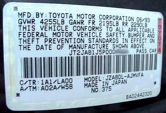
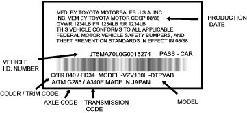
–When
identifying the correct part for your vehicle, it may be necessary
to know the production date, model number, engine number, color,
trim, axle or transmission code. The illustration above is an
example of a Vehicle Identification Label which is affixed to all
Toyota vehicle’s at the time of production.
– On passenger cars, the I.D. label is located on the inside of the
driver’s door.
– Vehicle Identification Numbers (V.I.N.)
contain 17 digits consisting of letters and numbers only. V.I.N.
numbers beginning with the letter “JT” were produced in Japan, all
others were produced in North America.
– Production
date information will appear on the Identification plate in the
following format: 08/88 for August of
1988
– Exterior color and interior trim code
numbers will appear together in the lower left corner, such as
033/KA41, with the digits to the left of the slash indicating the
exterior color code and the final four digits indicating the
interior trim code. The third and fourth digits of the interior trim
code indicates the interior color ( ie. KA41 = interior trim code #
41).
– Please remember that most manufacturers,
including Toyota, release new models in August each year. Therefore
a vehicle with a production date of 07/93 would be considered a 1993
model, whereas a vehicle with a production date of 08/93 would be
considered a 1994 model.
![]()
Jeff h. advice on brake pads
Jeff H.
Advice on Brake Pads
I’m writing this for the
street & everybody else that wants to do track days.You should use the stock pads for street driving. They
are easy on rotors
and have very good grip and dust is tolerable and they are reasonable in
price. anything else of higher performance will be a waste of money and
will tear up your cross drilled rotors. The next pad ‘I’ would choose
would
be the Hawk HP-S pads.
The S stands for street compound. They work well
for street use and are similar to the stock pads. Those are also the same
pads Brembo sells with their cross drilled rotorsAlso IMO you wasted money on your brake lines and fluid if
all you are
going to do is street driving. The lines are not visible and Dot 3 fluid
would have also been fine for street use. The Cross drilled rotors will
also be fine for street use and will look great. If you ever brake hard
enough to need the motul 600 then you will crack those rotors for sure.
The street is the only place for those rotors because they will crack.
Trust me I have done it.
Supra brakes are awesome but you do have some compromises
depending on
what you want to do with them. The stock rotors are so cheap that for road
racing they are the way to go and use a harder more expensive pad.
Consider
the stock rotors disposable and use a pad like the Hawk
blue compound. The
car will out brake anything with that combo and will not fade assuming your
fluid is up to the task. You will replace the rotor with the pads (with a
slight chance at turning them) after 2 to 3 track events depending on the
track and braking needed on the particular track. Next consider cryo
treatment of the rotors to prolong the life of the rotor. Pads I hated
for
street or track? I hated the TRD pads. Hawk
black pads were OK but took
too much time for me to warm them up. Hawk
HP plus are a street / track
combo pad. I had trouble getting them to hold up under hard braking and
after a day of hard braking at a track day they would come apart and
crumble. They were OK at TWS but you don’t use the brakes much there
compared to some tracks like Hallett.
I don’t think the big brake upgrades are cost effective
because if you
are using them for track days you will continue to need to replace the
rotors and pads which are MUCH more expensive. Remember the stock brake
components are cheap. I have no experience with the big brake upgrades and
I have no doubt they stop very well but with the right pad rotor combo you
can also. I already worry about collecting some Porsche, corvette or viper
that underestimates their brakes and rams into me in a tight corner after
the pass of course 🙂Jeff Hood
jkhood@cableone.net
Some Cryo links:
![]()
Clutch installation(6-spd)
Clutch Installation
(6-SPEED)
By Chris Bergemann @ HorsepowerFreaks.com
I unfortunately seemed to have been the test bed for many different aftermarket clutches, all which have
failed prematurely. I have taken my transmission out way too many times.Here are some examples of clutches that will work at different horsepower levels.
Clutch Kits Engagement (1=stock – 10=on/off switch Drag Racing Use 290-350rwhp Toyota stock Pressure plate and Disk 1 – light pedal feel, nice smooth engagement 350-500rwhp ACT HD Pressure Plate w/Stock Disk (max 550rwhp) 1 – medium pedal feel, nice smooth engagement Yes
RPS “MAX” Pressure Plate w/Stock Disk (max 500rwhp) 1 – medium pedal feel, nice smooth engagement Yes
TRD Single Disk (max 500rwhp) 1 – medium pedal feel, nice smooth engagement Yes
500-650rwhp ACT HD Pressure Plate w/HPF Disk 3 – medium pedal feel, smooth but short (1″) engagement Yes
RPS “Max” Pressure Plate w/RPS sprung Disk 3 – medium pedal feel, smooth but short (1″) engagement RPS or ACT Pressure Plate w/AZ Disk 7 – medium pedal feel, rough and short engagement below 2,000rpm Yes
South Bend Pressure Plate w/Dual Friction Disk 4 – light pedal feel, smooth but short (1″) engagement Yes
RPS Carbon Carbon Twin Disk 5 – medium-heavy pedal feel, a little rough and short (1″) engagement Yes
TRD Twin Disk 8 – medium pedal feel, very short and harsh engagement OS Giken Twin Disk 10 – heavy pedal feel, very short and harsh engagement – on/off switch Exedy Twin Disk 4 – light pedal feel Yes 650-900rwhp ACT HD Pressure Plate w/HPF Bronze Disk 3 – medium pedal feel, smooth but short (1″) engagement Yes
RPS Carbon Carbon Twin Disk 8 – light pedal feel, rough and short (0.5″) engagement Yes
OS Giken Triple Disk 10 – heavy pedal feel, very short and harsh engagement – on/off switch HKS Triple Disk 10 – light pedal feel, very short and harsh engagement – on/off switch Tilton Triple Disk 1 – light pedal feel, medium tough engagement, very expensive Yes
WOTM Clutch w/RPS PP 7 – medium pedal feel Yes
Exedy Triple Disk 1 – light pedal feel, mild engagement, not yet proven Yes
900rwhp+ Tilton Triple Disk 1 – light pedal feel, very smooth and easy engagement, very expensive Yes
HPF Feramic Clutch w/ACT PP 4 – medium pedal feel, very smooth and easy engagement Yes
Shown below is an ACT Heavy Duty Pressure plate and various disks. ACT Pressure plates are yellow, RPS Pressure plates are
blue. Disks can either be sprung or unsprung as shown in the picture below. A sprung disk has springs in the disk to provide
a cushioning effect to minimize drive-train stress on engagement. It’s best to run a sprung disk if you’re going to use a
lightened flywheel. The stock “dual mass” flywheel has cushioning built into the flywheel, however it’s heavy 34lb weight
causes an approximate 20rwhp loss across the entire RPM range.
Show below from left to right is the stock flywheel, pilot bearing, RPS clutch disk,
throw out bearing and Toyota pressure plate.
Fidanza makes a reasonably prices lightened flywheel that will make a noticeable increase in power in your Supra. It comes at
the expense of tranny rattle between 800rpm and 1,100rpm. I’ve set my idle to 1,350 and there is no rattle. You can also
press the clutch pedal in when stopped to avoid this rattle as well. This tranny rattle can sound as bad as a diesel truck,
however on some cars it is barely noticeable.If you wish to re-use your stock flywheel, don’t make the mistake I original did. I had the flywheel “wet” turned. When
they “wet” turned it, they used radiator fluid to keep the cutting process cool. This sent
tons of metal shavings and fluid down into the rubber part of the flywheel. Of course, I installed it later, and found
out that the rubber in the flywheel is actually used for something. Go figure. If you want to re-use your original flywheel
you need to ensure that the rubber in it is still good. Once the transmission is removed (as described below)
make sure that the rubber is still good, by attempting to turn the flywheel more than 2 inches either way while it is bolted
to your crankshaft. If you can’t, then
the rubber is still good and you may be able to re-use it. Then you need to have a shop turn it “dry” (no fluid),
and make sure you cover all interal areas with duct tape or something that can handle the heat, so that nothing gets down into that rubber.Prior to putting that nice polished looking flywheel and pressure plate in your car, make sure you sand the metal with some
100 grit sand paper to ruff it up. This will help the surfaces mate once installed.Now, if you want to do everything the easy way, get all the tools shown in the picture below. I apologize for the quality
of these first two pictures. They get better. From left to right are: breaker bar (hopefully won’t be needed), long and short screw
drivers, a bunch of metric sockets and wrenches from 10mm to 17mm, high power air gun (add 2 hours and 2 rounded bolts if
you don’t have this), pilot bearing puller ($39, a must to get that little pilot bearing out), pipe wrench (yes a pipe wrench),
sideways rachet air tool (not necessary, only if lazy), regular jack (a tranny jack is not necessary) and 4 jack stands (can get by with 2 if that’s all you have).
To make life easy, I always jack up the car fairly high, and put it on 4 jack-stands. The sides of the car need to be atleast
one foot in the air if you wish to pull the tranny out the side (recommended). If you only have 2 jack-stands, use them to support the front of the
car.
First, disconnect the negative side of the battery. (As the starter will be taken out later)
Nextwe need to dismantle the shifter, so the transmission can be lowered. Simply pull up on the center console as shown
below, and disconnect all the attachments to it.
Take the shifter knob off. Undo the 4 bolts (10mm), remove metal bracket and pull the rubber up over the top.
Now, crawl under the car, and remove the O2 sensor from the downpipe (or catalytic converter pipes). There are 2 12mm bolts holding it on.
When you get it out, do not touch the part of the O2 sensor that was previously inside the exhaust pipe.
Take off the downpipe (or catalytic converter) which ever one you have by removing the 2
bolts connecting it to the exhaust manifold (Note the picture shows Rod Millen downpipe and a Greddy exhaust).
(use either one 14mm wrench and an air gun w/14mm socket & extension, or 2 14mm wrenches) Hang on to the exhaust
manifold when the bolts are removed so it doesn’t hit the ground hard.
Now remove the 3 14mm bolts connecting it to the header, and the one bolt “if used” connecting it to a bracket.
Use 2 extensions, and an air gun. 6 sided
sockets are preferable to 12 pt ones, as they won’t round off the bolts if you don’t get them on just right.
The downpipe is much easier to take off then the catalytic converter because there is more room to get the
extensions through (the downpipe is shown in the picture below). If you don’t have an air gun for this one, I’m sorry.
Now remove the metal tray that is above the exhaust, by removing the 4 10mm bolts holding it in place. This will expose
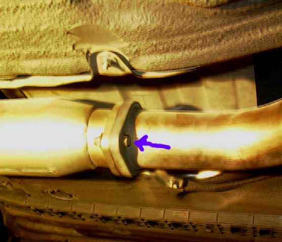
all of the driveline you need to see. Put the transmission in gear, and set the parking brake. Now, use a pipe wrench to
remove the large nut on the driveline. The bottom of the wrench should be pushed from driver’s side to passenger’s side
to loosen the nut. Then remove the two bolts holding the rear of the 2′ driveline. Now pull the rubber back where the
large nut was, and mark the axle and the splines so you can line them up the same when when installing. Also, mark the
front of the drive axle where it connects to the tranmission yolk.
Now remove the 4 14mm bolts on the front of the drive axle with a 14mm wrench. Use the parking brake and transmission
shifter to allow the driveline to turn and to keep it from turning. (Note, the rear wheels must be in the air for this to occur).Now remove the transmission crossmember by removing the 4 14mm bolts holding it up. The transmission will drop down about 3
inches once this is removed. Now, pull the driveline out.
Now remove the electrical connectors going to the transmission. There is one connector on each side of the transmission.
On the side of the connector going to the car, unhook it from all the clips affixing it to the transmission.Now remove the clutch linkage. Remove the two bolts holding the clutch cylinder to the transmission, and remove the bolt
holding the ground wire, and clutch line to the transmission. Note: you do not need to remove the C-clip.
Now remove the starter. First disconnect the black electrical connector. Then remove the bolt holding the positive
cable to the starter. (Did you remember to disconnect the battery?) Now remove the 2 14mm bolts holding the starter to the
transmission. They are near the top of the transmission, and the best way to take them out is to use a 14mm socket, 4 extensions and
an air gun.
Now remove the two black viewing covers each held by 2 12mm bolts, on the bottom of the tranmission towards the front of the car.
Removing those will allow you to get at the clutch.Inside those two holes created once the covers are removed, you should be able to see the back
of the pressure plate. That pressure plate is held to the flywheel by 6 12mm bolts. In between the pressure plate and
the flywheel is the clutch. If you are going to reuse the pressure plate, flywheel and clutch, mark a white line, so
you can line them up later.Remove the 6 bolts holding the pressure plate to the flywheel. Loosten them a little at a time. When re-installing
later, make sure you tighten them a little at a time, working your way around the pressure plate. You will need that
big screw driver to turn the clutch so you can get at the other bolts. I use the brute force method, and simply push.Once you have removed the 6 bolts, pull the pressure plate back, and make sure it is disengaged from the flywheel. You
should be able to spin it by hand.Important: Do not confuse these 6 12mm bolts with the other 12mm bolts when installing the clutch later.
They look alike, except the pressure plate
bolts have a “7” on the head of them. If you try to put the other 12mm bolt in the pressure plate, and tighten it,
you will break it off in your flywheel. Trust me on this one, I know by experience.Now we’re ready to remove the transmission. Remove the 3 14mm bolts on the bottom of the transmission where it
is bolted to the engine. 2 are facing the front of the car, one is facing the back of the car.Now, remove all of the big 17mm bolts except one around the transmission housing. Leave one in there so the tranny doesn’t
fall. Then, put a jack under the transmission, making sure it is holding the transmission, but with no upward force applied and
remove the last 17mm bolt. The best way to do this is with a 17mm
socket, 4 extensions and a high powered air gun. (Believe it or not, with this method, I can take all the 17mm bolts
out in 2 minutes) The transmission should easily come apart from the engine. If it doesn’t, there’s probably still
a bolt left to remove. Now, lower the transmission to the ground, and carefully move it out from underneath your
car.Now, its time to take off the flywheel. Use a 12 pt 14mm socket to remove the 8 flywheel bolts. I strongly recommend
using an air gun (Without an air-gun you will need to use some device to keep the engine from turning.)Now, remember that strange tool in the 2nd picture next to the pipe wrench. That’s a pilot bearing removal tool. You
will need this to remove the pilot bearing shown in the center of the next picture. If you leave this bearing in.. as I
did many times, you may get premature clutch failure, and prolonged clutch chattering.While you’re here, hammer the new pilot bearing into the flywheel. Make sure it goes in as far as possible.
There’s a fork in the side of your transmission that holds your pressure plate in place. It is what moves when
you press your clutch in. Pull this fork out by hand. Wiggle it until it comes out.
Pull the pressure plate and clutch out of the front of the transmission. It should slide off once the fork is removed. There are two C clips
holding the pressure plate to the throwout bearing and sleeve. Remove the C-clips and the old throw-out bearing (remember
how it goes back together)Did you roughen up the new pressure plate and flywheel? (use 100 grit sandpaper to do this), then clean both with brake
cleaner. It is imperative that no oil/grease/dirt is on the contact surfaces of the flywheel, pressure plate or clutch
when assembled.Install the new throw-out bearing onto the new pressure plate using the old sleeve, C-clips
and circular disks. Note: one of those disks is not flat. it’s supposed to be that way.Put some extreme pressure, high-temp grease on the wear parts of the fork (be careful not to put on too much,
and not to get the grease any where the clutch might contact), and install the new pressure plate and fork
on the transmission.Carefully move the transmission under the car, and install in the reverse order.
Points to remember on installation:
Do not get anything on clutch and clutch contact surfaces. Do not use the wrong
12mm bolts on the pressure plate or they will break off in the flywheel. They should be marked with a “7”. Install
pressure plate bolts evenly and a little at a time working your way around. Line up marks on driveline when installing.
Do
not squish wires between transmission and engine (I know this one from experience also).
Do not overtighten positive
cable bolt on starter (starter housing will break). Make sure all rubber boots are firmly around whatever they are
protecting, or things will rust.On all aftermarket disks, the cone section faces the rear of the car. This is opposite of the stock disk shown in the picture.
If you can’t get your car in gear after installing your new clutch, you may need to adjust your clutch pedal. Do this
by loosening the nut near the top of your pedal, and twising the metal bar, until the clutch engagement feels
comfortable for you.Make sure you drive slowly for 200 miles (on new RPS clutches) or 500 miles (for other clutches) to break it in, and
seat the mating surfaces.
Torque #:
- Flywheel to Crank: Tighten to 36 ftlb in
a crossover pattern, then tighten each bolt another 90 degrees again in
pattern. If you are doing this with an aluminum flywheel, make three
passes at 36 ftlb before the 90 degree tighten, the aluminum will compress a
little (AMHIK).- Pressure plate to flywheel: 14 ftlb (I recommend 20ft-lbs or more). (I normally use a 12mm little wrench and tighten as tight as I can. If these back out, your clutch will be toast within a few miles)
- Transmission to engine: 17mm head bolts,
53 ftlb; 14 mm head bolt, 29 ftlb.- Starter terminal is 48 inlb (Notice the
units!)- Starter bolts: 29 ftlbs
- Release Cylinder: 9 ftlbs
- Clutch housing covers: 9 ftlbs
- Center support bearing mounts: 36 ftlb
- Intermediate shaft to transmission bolts:
41 ftlb- Rear transmission mount inside bolts: 10
ftlb- Rear transmission mount outside bolts:
19 ftlb- Shifter pivot bolt: 14 ftlb
- Shifter plate bolts: 69 inlb
- Crossmember bolts: 9 ftlb
Comments/suggestions? Email me


Rear wheel bearing replacement
Rear Wheel Bearing Replacement
If you hear funny sounds from the rear of the car, and cannot see where the noise is coming from, you may have a
rear wheel bearing failure like I did. Hopefully you don’t! This was caused by the nut on the hub being finger tight, rather
than the recommended 213 ft-lbs.
To install a new rear wheel bearing yourself, you need a lot of patience, 2 breaker bars or long wrenches, snap ring removal
tool, air-gun is helpful, assorted metric sockets, wrenches, a large hammer, screwdriver, 14mm allen socket, 10mm allen socket,
and a nearby shop that is willing to press the old bearings out of the housing, and press the new ones in.
For parts, you will need new wheel bearings, the inner and outer oil seal. If the Hub is bad, you will need a new Hub as well.
Begin by jacking up the rear of the car, and removing the rear tire. Note: All of my pictures are from the right (passenger) side.
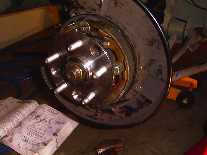
Remove the cotter pin in the end of the hub, and remove the funny looking nut cover. Remove the Hub Nut. This is where
an air gun comes in handy. Otherwise you may need to have someone press on the brakes while you remove the hub nut. Now go under
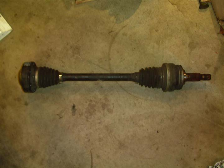
the car and remove the 6 bolts holding the drive axle to the differential. You will need a 10mm metric allen socket. Then
push the axle towards the wheel, and pull the axle out of the differential.
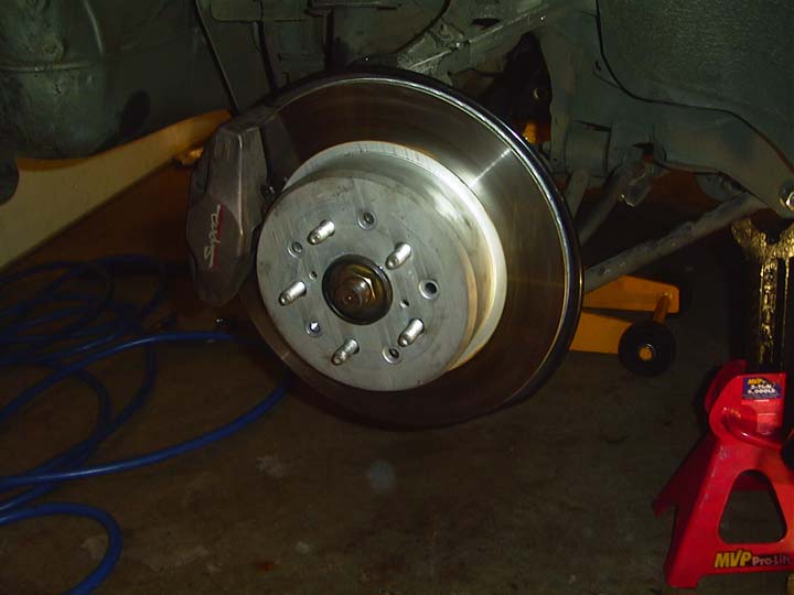
Remove the 2 bolts on the back of the brake caliper, and slide the caliper off. Make sure the parking brake is off, so the disk
can be removed. Try to pull the disk off. If it cannot be pulled off earily, get two small long metric bolts and screw them into the
little holes in the brake disk until the brake disk comes off.
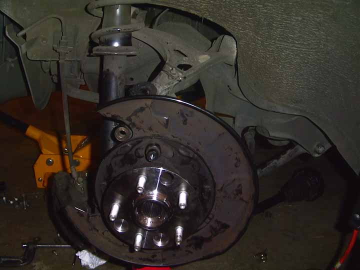
Now unhook, unbolt and remove the parking brake shoes.
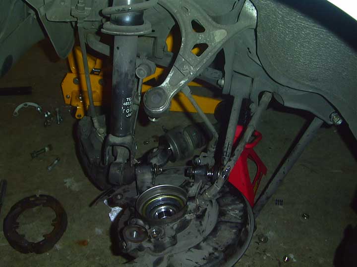
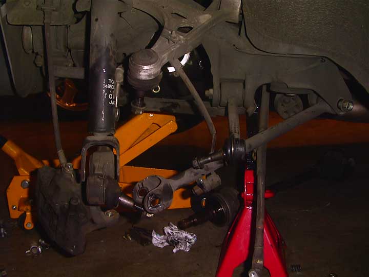
Now the fun part. Remove all the
bolts holding the housing in the car. I used a large breaker bar and jumped on the end of
it to get them free. Once the nuts were off, I carefully used a hammer to separate the
ball joints from the housing. Note: I did not remove any other suspension bolts, other than
the ones on the housing.
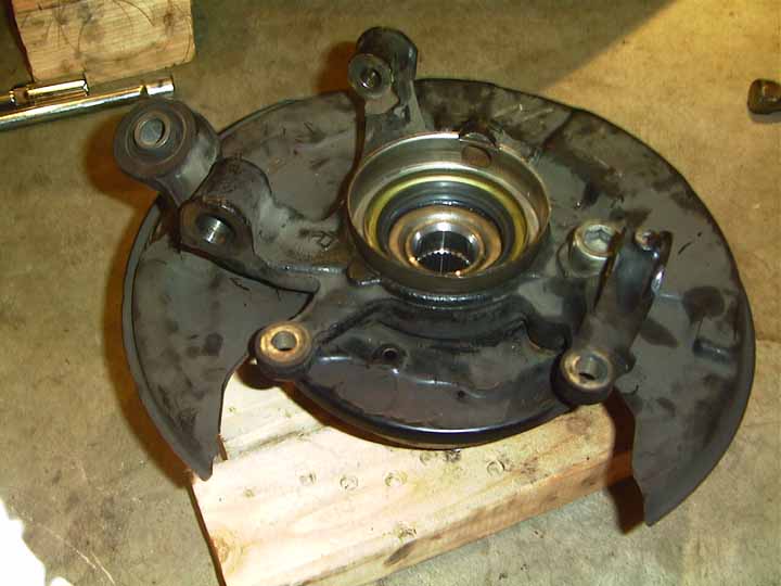
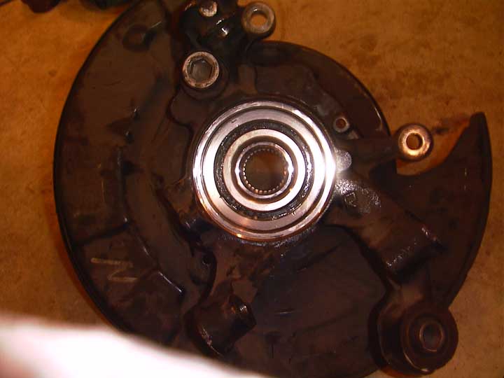
Now disconnect the parking brake cable from the housing, and remove the housing from the car.
Here’s the housing. “Note the Hub has already been removed – mine fell out” If yours does not
come out, have the shop pull it out for you.
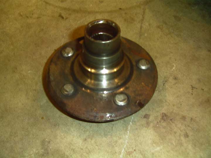
Here’s the BAD Hub. Notice how the diameter increases about one inch down the shaft. It should
be the same all the way down.
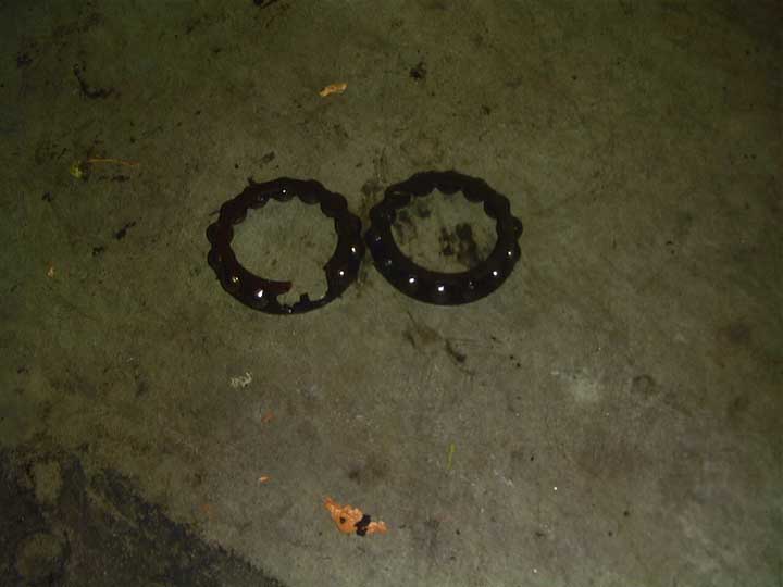
Here’s are the bad bearings.
Now pull the seal out of both ends of the housing, and remove the metal edge. Use a snap
ring remover, and remove the snap ring from the other end.
Take the housing to the shop and have the old bearings pressed out, (and the Hub if you can’t get it out),
and have the new bearings pressed in. (Do not have the Hub pressed back in yet!)
Before you put the hub back into the housing, mount the brake guard back on the Hub with the big
allen bolt. Also… Put the snap ring back in, and put a new seal in both the front and back ends.
Now put the Hub back in. I used some blocks of wood, and a sledge hammer to pound the
Hub into the Housing. Then add the metal lip back to the inner side of the housing.
Now install everything in the reverse order.
Also check out the Toyota
Repair Manual
Comments/suggestions? Email me
Suspension spring rates
| JZA80 Suspension: | |||||||||
| Spring | Type | Front lbf/in | Rear lbf/in | % stiffer than Stock Front | % stiffer than Stock Rear | Height Drop Front | Height Drop Rear | AVG. Price | |
| ———————————————————————————————————————————————————————————————————————————————————————- | |||||||||
| Stock | linear | 430 | 219 | ||||||
| Eibach | proggressive | 370->510 | 180->263 | 18.6 | 20.1 | 1.2 | 1 | $220 | |
| H&R | progressive / linear | 470->495 | 250 | 15.1 | 15.2 | 1.1 | 1 | $240 | |
| Greddy* | ? springs | 509.6 | 240.8 | 18.5 | 10.0 | ? | ? | ||
| Intrax | progressive (see new notes below) | 559 | 285 | 30.0 | 30.1 | 1.5 | 1.3 | $247 | |
| HKS | ? springs | 573 | 254 | 33.3 | 16.0 | 1.4 | 0.2 | ||
| HKS 10-way* | coilover | 661 | 386 | 53.7 | 76.3 | NA | NA | ||
| HKS 20-way* | coilover | 661 | 386 | 53.7 | 76.3 | NA | NA | ||
| Blitz | coilover (sachs damper options) | 685 | 571 | 59.3 | 160.7 | NA | NA | ||
| HKS Hiper Max II | coilover | 772 | 441 | 79.5 | 101.4 | NA | NA | ||
| HKS30-way | coilover | 772 | 441 | 79.5 | 101.4 | NA | NA | ||
| HKS Drag | coilover | 772 | 220 | 79.5 | 0.5 | NA | NA | ||
| Tein | coilover | 780 | 450 | 81.4 | 105.5 | NA | NA | ||
| Tanabe | coilover | 784 | 672 | 82.3 | 206.8 | NA | NA | ||
| Intrax | coilover | ? | ? | NA | NA | ||||
| Ground Control | coilover | 950 | 600 | 120.9 | 174.0 | NA | NA | ||
| H&R | coilover | ? | ? | ||||||
| * = discontinued | |||||||||
| Original spreadsheet credits: Kent Rafferty / Andi Baritchi |
|||||||||
| Some data courtesy of Dusty Womack www.mvpmotorsports.com |
|||||||||
| Last revision & additions -2/02- Derek Steffey pacnw.supras.org |
|||||||||
| Intrax spring data – 2/11/02 – Intrax says front spring is linear @ 350lbf/in and rear is progressive from 152->285 |
|||||||||
| Intrax R Heigth (mm) | Intrax R Loading (N) (off vehicle) | 1N/mm = 5.7 lbf/in | |||||||
| 300 | 0 | 0 | |||||||
| 260 | 1000 | 21.96153846 | |||||||
| 200 | 2600 | 74.23 | |||||||
| 180 | 3250 | 103.0972222 | |||||||
| 140 | 4750 | 193.7321429 | |||||||
| 120 | 5750 | 273.6041667 | |||||||
| (-note: This data seems suspect, though Intrax Claims it is correct for currently shipping springs for MKIV Turbo models.) |
|||||||||
how to replace spark plugs on supra twin turbo
How
to Replace Spark Plugs on Supra Twin Turbo
1)
Buy 6 New spark plugs, you have a choice of stock plug or any of your favorite
plug on the market,– Here is a list of the most commonly used spark
plugs,
- Stock Denso PK20R11, Comes pre-gaped at
0.043 inch (best on stock supra)- Stock NGK BKR6EP-11 (2978), Comes pre-gaped
at 0.043 inch (best on stock supra)- NGK BKR7E (6097), Comes pre-gaped at 0.032
inch (best on BPU & APU supra)- NGK BCPR7ES (3330), Comes pre-gaped at
0.032 inch (best on BPU & APU supra)– Also buy 2 crankcase
hoses, Toyota part number 12263-46010 & 12264-46010 (if needed),
if you have not replaced your hoses in a long time, chances are you going to
have a hardened crankcase hoses that will get damaged on removal, its always a
good idea to save new ones just in case you need them one day.
2) Remove the oil
cap and plug up the hole with a towel so you don’t drop anything down the oil
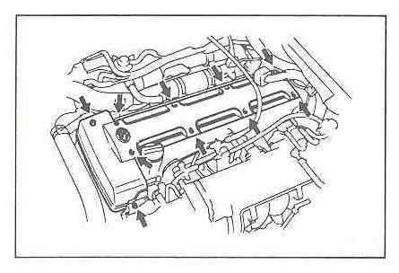
hole accidentally.3) With an Allen wrench(5mm) remove the top
cover of the engine, 10 screws. This best done on a cold motor.
4) Remove the two crankcase vent
hoses that run between the valve covers. if they are hard to come off, clamp
them in the middle with pliers and twist the hose.
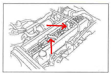
5) Using a small flat
head screwdriver, release
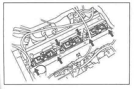
the wiring harness clips.6) Disconnect wiring
from the coil packs. two connectors per coil packs.7) Unbolt the coil packs holders. there
is a 10mm bolt on each side of the coil packs holders. there are 3 coil packs
holders.
8) Lift out the coil packs holders. Rock them back and forth if they are hard to come out, that will
help them come loose.
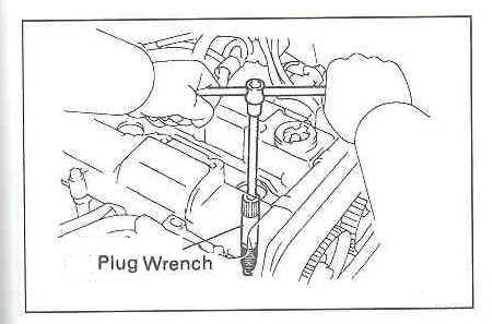
9) Use a deep well 5/8th spark plug socket to
remove plugs.
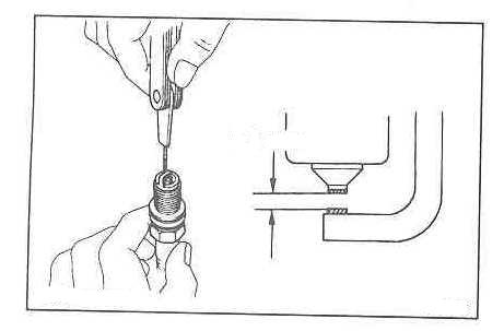
10) Gap (if needed)
& install the
new plugs (torque it to ~13 ft/lbs). or as shown on the manufacture interactions.
11) Install the coil packs. Make sure they are
seated.12) Connect wiring and re-clip wiring harness to clip. make sure each harness routes *below* the crankcase
vent.13) install crankcase hoses that you
bought (or previous ones if they are not cracked).14)
re-install cover and cover screws.15)
Remove towel from oil hole and replace it with the oil cap.
– Damaged your Coil Harness? Click Here
– All You Ever Wanted to Know About
NGK Plugs!


how to replace spark plugs on supra twin turbo
How
to Replace Spark Plugs on Supra Twin Turbo
1)
Buy 6 New spark plugs, you have a choice of stock plug or any of your favorite
plug on the market,– Here is a list of the most commonly used spark
plugs,
- Stock Denso PK20R11, Comes pre-gaped at
0.043 inch (best on stock supra)- Stock NGK BKR6EP-11 (2978), Comes pre-gaped
at 0.043 inch (best on stock supra)- NGK BKR7E (6097), Comes pre-gaped at 0.032
inch (best on BPU & APU supra)- NGK BCPR7ES (3330), Comes pre-gaped at
0.032 inch (best on BPU & APU supra)– Also buy 2 crankcase
hoses, Toyota part number 12263-46010 & 12264-46010 (if needed),
if you have not replaced your hoses in a long time, chances are you going to
have a hardened crankcase hoses that will get damaged on removal, its always a
good idea to save new ones just in case you need them one day.
2) Remove the oil
cap and plug up the hole with a towel so you don’t drop anything down the oil
hole accidentally.3) With an Allen wrench(5mm) remove the top
cover of the engine, 10 screws. This best done on a cold motor.
4) Remove the two crankcase vent
hoses that run between the valve covers. if they are hard to come off, clamp
them in the middle with pliers and twist the hose.
5) Using a small flat
head screwdriver, release
the wiring harness clips.6) Disconnect wiring
from the coil packs. two connectors per coil packs.7) Unbolt the coil packs holders. there
is a 10mm bolt on each side of the coil packs holders. there are 3 coil packs
holders.
8) Lift out the coil packs holders. Rock them back and forth if they are hard to come out, that will
help them come loose.
9) Use a deep well 5/8th spark plug socket to
remove plugs.
10) Gap (if needed)
& install the
new plugs (torque it to ~13 ft/lbs). or as shown on the manufacture interactions.
11) Install the coil packs. Make sure they are
seated.12) Connect wiring and re-clip wiring harness to clip. make sure each harness routes *below* the crankcase
vent.13) install crankcase hoses that you
bought (or previous ones if they are not cracked).14)
re-install cover and cover screws.15)
Remove towel from oil hole and replace it with the oil cap.
– Damaged your Coil Harness? Click Here
– All You Ever Wanted to Know About
NGK Plugs!