Why
the GReddy BCC? The reason that the MkIV owners recommend the GReddy BCC over the HKS Fuel Cut Defensor (FCD)and the Free Fuel Cut Defensor (FFCD) is simple. The HKS unit reduces the signal coming from the turbo pressure sensor at a fixed percentage, which means that all the data coming from this sensor is corrupt. The FFCD fixes the value coming from the turbo pressure sensor at something close to atmospheric by capping the pressure input to the sensor. The turbo pressure sensor is used for six different functions by the ECU. The most noticeable is fuel cut for an overpressure condition which is 2.00 kg/cm2 absolute pressure, or 0.97 kg/cm2 gauge (28.45 psia, 13.75 psig). Fuel cut is an extreme measure invoked by the ECU when it detects boost over 2.00 kg/cm2 absolute, AND throttle position 20 degrees or more AND engine speed over 2400 rpm. It shuts down the engine until the boost drops back below the 2.00 kg/cm2 threshold, and lights up your MIL (malfunction indicator light). The other turbo pressure sensor functions are exhaust gas bypass valve control, idle speed anticipation, exhaust gas recirculation (EGR) control, fuel pump voltage selection, and evaporative emissions control. Of critical note is the use of the signal for the exhaust gas bypass valve. This valve (referred to on the list as the EBV) is used by the ECU to control boost pressure from the #1 turbo while below 3500 rpm. The ECU uses the turbo pressure sensor input to modulate the EBV in the same way as a wastegate to control boost from #1 and also to prespin turbo #2 in anticipation of bringing #2 on line. This prespin also minimizes the impact of full exhaust gas pressure suddenly being applied to the #2 turbo at the transition point. It is believed that the sudden spool up of the #2 turbo could contribute to what the list calls "the death whine" or #2 turbo failure. The HKS FCD and the FFCD either modify or eliminate this feedback to the ECU and put the EBV in fail-safe mode which fully opens the EBV at only 2500 rpm. This causes a severe drop in boost at the transition between single and twin turbo operation, some owners have seen boost drops to as low as 5 psi before the #2 turbo comes on line, then sudden spikes as high as 17 and 18 psi that will really make you think that you have more power when in fact you are killing your midrange power and then suddenly bringing back full power. While not damaging to the turbos because you are providing plenty of prespool to the #2 turbo, it really masks the true potential of the car, and makes the car harder to drive smoothly. List members have also experienced trouble with detonation from lack of fuel pressure (this was what led to the 12v fuel system mod), erratic idle speed, and have burned spark plugs from EGR at inopportune times. While not directly attributed to the FFCD, these kinds of problems were common place among FFCD users running over 18 psi boost. The Greddy BCC does not alter the signal significantly (I measured a 2.0 millivolt gain) and clamps the signal at a preset voltage that is user adjustable over a fairly wide range. It keeps all the stock functions operating properly, and avoids the sudden shutdown caused by fuel cut when the car exceeds the ECU's maximum boost value. It is well made, and should prove quite reliable over the long haul. GReddy Boost Cut
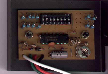
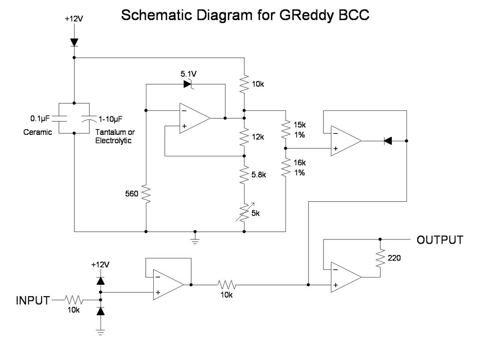
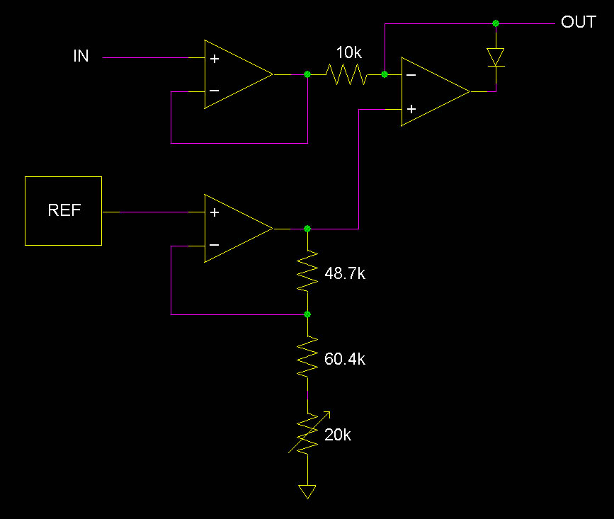
Controller (BCC) Notes: All testing performed with supply voltages 14.50 vdc and lower using Lambda LCS-C-15R supply adjusted for 14.50 vdc as measured with Fluke 8024 Digital Voltmeter (DVM). All output measurements were taken without a load. There is no reason to believe that the ECU will provide any significant loading to the BCC. Factory Settings: Unit under test provides 2 millivolts gain to the signal, which equates to 0.016 psi, across all test voltages. This is insignificant. The unit clamped @ 3.94 vdc which equates to 0.71 kg/cm2 or 10.12 psi gauge according to measurements taken on my OEM turbo pressure sensor. I reset the clamp voltage to 4.31 vdc to simulate 1.95 kg/cm2 absolute pressure, since the manual states that fuel cut occurs at 2.00 kg/cm2 absolute. This clamp setting equates to 0.92 kg/cm2 gauge or 13.04 psig. I tested the stability of the unit's output with varying supply voltages. The output remained stable until supply voltage dropped below 10 vdc, and full control resumed at 10.75 vdc worst case. This is well below battery voltage. GReddy could have made the unit approximately 1/3 smaller by using dedicated resistors and hardwire instead of the DIP switch and resistor array. I removed the extra resistors and the DIP pack from my unit and replaced the switch with a wire. The tests were completed with this configuration. The alternate resistors are for other applications, but GReddy does all the adjustments at their facility and marks the units according to the switch settings and adjustment of the variable resistor. I did not test the unit with a frequency generator to measure response time since the highest frequency that could be expected is around 350 Hz for a stock engine and 450 Hz for a radically modified engine. The unit is capable of response well beyond these numbers. The choice of integrated circuit is curious. Texas Instruments, the manufacturer, also makes a quad op amp specifically for a wider temperature range in automotive applications, but GReddy chose not to use this. There is also a MIL SPEC version of this chip available with the full -55 to +125 C temperature range. This unit should be installed in the passenger compartment, NOT UNDER THE HOOD! It is not waterproof and will not withstand high heat or extreme cold. The chip is rated from 0 to 70 C only. The Unit is well constructed and extremely stable. It far surpasses the performance of the equivalent HKS device since it passes all data uncorrupted until it hits cutoff, unlike the HKS which reduces the data by a constant percentage. BCC Circuit By Lance W.
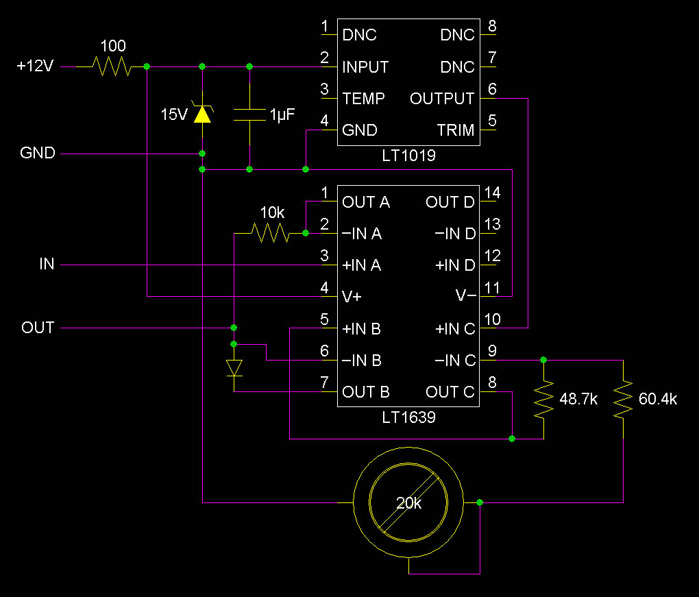
BCC Circuit By Bill
<bill439@yahoo.com>
Turbo Pressure Sensor Notes:
Test performed with unit connected to the ECU and a 60cc syringe used as a pressure source. Pressure indication performed by Blitz Dual Turbo Timer boost gauge. ECU output to the sensor is well regulated at 5.00 vdc, and did not change even under starting conditions. This voltage output also supplies the two throttle position sensors. After plotting 91 data points of both pressure and vacuum, loading the numbers into a spreadsheet and plotting the chart with interpolation between points, I have arrived at a simple formula to calculate output voltage based on input pressure. It is Vout=(1.8125*P)+0.7776, where P is in kg/cm2 absolute, and Vout is vdc. Conversions for kg/cm2 are: Conversions courtesy The Handbook of Chemistry and Physics, 61st Edition.
|